p.
6
- M
anu
al
FA
0
0
9
4
5
-E
N
- 0
1/
2
0
18 - © C
A
M
E S
.p
.A
. - T
ransla
te
d o
riginal inst
ru
ct
io
ns
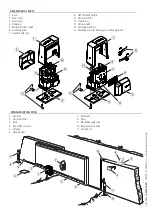
STANDARD INSTALLATION
1. Operator
2. Limit-switch
fins
3. Rack
4. Key-switch
selector
5. Antenna
6. Flashing
light
7. Photocells
8. Posts
9. Mechanical gate stop
10. Sensitive safety-edge
11. Junction pit
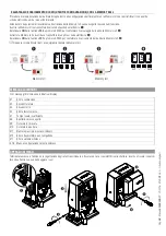
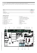
DESCRIPTION OF PARTS
1. Cover
2. Front
cover
3. Gear
motor
4. Condenser
5. Mechanical limit switch
6. Anchoring
plate
7. Control board rack
8. ZBX7N control board
9. Limit-switch
fins
10. Transformer
11. Release hatch
12. Fastening hardware
13. Mounting brace for housing accessories (optional)
Summary of Contents for BX Series
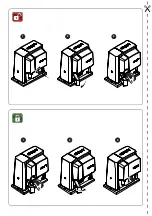
Page 2: ...2 3 1 2 3 1 ...
Page 30: ...2 3 1 2 3 1 ...
Page 58: ...2 3 1 2 3 1 ...
Page 86: ...2 3 1 2 3 1 ...

