background image

1

2

3

4

5

6

7

8

9

10

11

12

13

14

15

16

17

18

19

20

21

22

23

24

25

26

27

1

2

3

4

5

6

7

8

9

10

11

12

13

14

15

16

17

18

19

20

21

22

23

24

25

26

27

  i

U

  2

  5

p.


22

 - M

anu

al 

FA

0

1

2

0

8

-E

N

 - 0

7/

2

0

21 - © C

A

M

E S

.p

.A

. - T

ransla

te

d o

riginal inst

ru

ct

io

ns

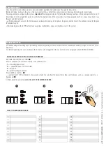
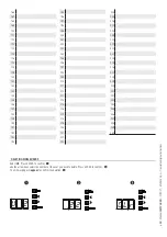
LIST OF REGISTERED USERS

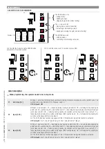
ENTERING USERS WITH AN ASSOCIATED COMMAND

Select 

U1

. Press ENTER to confirm. 

Select a command to associate to the user: The commands are:

1

 = step-step (open-close);

2

 = - sequential (open-stop-close-stop);

3

 = only open;

4

 = partial opening/pedestrian.

Press ENTER to confirm... 

... a number from 1 to 25 will blink for a few seconds. Send the code from the transmitter or other control device, such as, a keypad selector or a 
transponder.

Note down the user entered 

into the LIST OF REGISTERED USERS

.

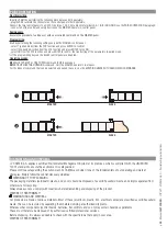
MANAGING USERS

 When adding and deleting users, the flashing numbers appearing are those numbers that are available and usable to assign to a new user (max. 

250 users).

Before registering the users, make sure the AF radio card is plugged into the connector (see the paragraph called CONTROL DEVICES).

COMMISSIONING

Once the electrical connections are done, have only skilled, qualified staff commission the operator into service.
Before continuing, make sure the area is free of any obstructions, and that there are mechanical, opening and closing gate stops in place.
Power up and begin configuring the system. 

Important!

 Start programming by first doing the following functions: F54 (opening direction) and F1 

(Total Stop). Once the programming is done, verify that the operator and all the accessories are working properly.Use the < > keys to open and close 
the gate and ESC to stop it.

After powering up the system, the first maneuver is always the opening. In this phase, the gate cannot be closed. You will need to wait for the gate 

to completely open.

⚠ 

Immediately press the STOP button if any suspicious malfunctions, noises or vibrations occur in the system.

Summary of Contents for BKS08ALS

Page 1: ...BKS08ALS BKS12ALS BKS18ALS BKS22ALS Sliding gate operator BK series INSTALLATION MANUAL EN English FA01208 EN...

Page 2: ...2 3 1 1 2 3 1...

Page 3: ...ace and free of any impediments to the gate s movement The rails of the upper guide must not cause any friction Make sure that opening and closing limiters are tted Make sure the operator is installed...

Page 4: ...PTION Operator fitted with control board and mechanical limit switches for sliding gates weighing up to 2 200 kilograms INTENDED USE The operator is designed to power sliding gates used in apartment b...

Page 5: ...ns Number of cycles Length of gate m Number of cycles Length of gate m Consecutive cycles graph Cycles hour graph DUTY CYCLES Datum BKS08ALS 12ALS 18ALS 22ALS Cycles hour no 14 Consecutive cycles no 1...

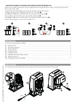
Page 6: ...tocells 8 Small post 9 Mechanical gate stop 10 Sensitive safety edge 11 Junction pit DESCRIPTION OF PARTS 1 Cover 2 Front cover 3 Gear motor 4 Fan BKS08ALS series 5 Condenser 6 Mechanical limit switch...

Page 7: ...ES AND MINIMUM THICKNESSES Connection cable length 20 m 20 30 m Input voltage for 230 V AC control board 1P N PE 3G x 1 5 mm 2 3G x 2 5 mm 2 Flashing light 2 x 0 5 mm 2 Command and control devices 2 x...

Page 8: ...surface Wait at least 24 hrs for the concrete to solidify Fit the bolts into the anchoring plate and tighten them using the nuts Remove the pre shaped clamps using a screw driver or pliers Fit the pl...

Page 9: ...AME S p A Translated original instructions Remove the foundation frame and fill the hole with earth around the concrete block Remove the nuts from the bolts Fit the electric cables into the tubes so t...

Page 10: ...he operator on top of the anchoring plate Caution The electric cables must pass under the gearmotor casing and must not touch any parts that may overheat during use such as the motor or the transforme...

Page 11: ...zontal adjustment This prevents the gate s weight from bearing down on the operator FASTENING THE RACK If the rack is already set up the next step should be to adjust the rack and pinion coupling dist...

Page 12: ...the micro switch is activated spring and fasten it using the grub screws ESTABLISHING THE LIMIT SWITCH POINTS For opening open the gate t the opening limit switch tab onto the rack until the micro sw...

Page 13: ...13 RSE card slot 14 Connector for the R700 R800 R900 card 15 Programming buttons 16 Memory roll card slot 17 Display 18 Power supply on warning LED 19 Terminals for paired of CRP connection 20 Termina...

Page 14: ...ro switch Condenser 120 230V AC gear motor Control board brace cable glands Closing limit switch micro switch ELECTRICAL CONNECTIONS Connect all wires and cables in compliance with the law Before conn...

Page 15: ...ck White Red Flashing light connection output contact rated at 230 V AC 25 W max SIGNALING DEVICES Gate state warning output contact rated for 24 V AC 3 W max See function F10 Additional light connect...

Page 16: ...g in MAINTAINED ACTION mode the control device must be connected to 2 4 PARTIAL OPENING function from control device NO contact OPEN CLOSE INVERT step step function from control device NO contact Alte...

Page 17: ...losing during opening When the gate is opening opening the contact triggers the inversion of movement until the gate is completely closed C3 partial stop Stopping of the gate if it is moving with cons...

Page 18: ...ow up on the display as E17 Fit the RSE card WARNING For the system to work properly before fitting the control board you MUST CUT OFF THE POWER MAINS and remove any emergency batteries Serial RS485 c...

Page 19: ...Can associate C1 reopening during closing by photocells C2 reclosing during opening by photocells C3 partial stop C4 obstruction wait C7 reopening during closing by sensitive safety edges with clean c...

Page 20: ...on for an adjustable time of between 60 and 180 seconds To set the time see function F25 OFF default 1 Cycle 2 Courtesy F19 Automatic Closing Time The automatic closing wait starts when the opening li...

Page 21: ...see the instructions that come with the accessory This function only appears is the control board has been tted with a RIO CONN card OFF default P1 P1 P2 P2 P3 P3 P4 P4 F68 Wireless input RIO CELL T2...

Page 22: ...available and usable to assign to a new user max 250 users Before registering the users make sure the AF radio card is plugged into the connector see the paragraph called CONTROL DEVICES COMMISSIONING...

Page 23: ...87 88 89 90 91 92 93 94 95 96 97 98 99 100 101 102 103 104 105 106 107 108 109 110 111 112 113 114 115 116 117 118 119 120 121 122 123 124 125 126 127 128 129 130 131 132 133 134 135 136 137 138 139 1...

Page 24: ...219 220 221 222 223 224 225 226 227 228 229 230 231 232 233 234 235 236 237 238 239 240 241 242 243 244 245 246 247 248 249 250 2 U 2 2 C l p 24 Manual FA01208 EN 07 2021 CAME S p A Translated origina...

Page 25: ...the F50 and press ENTER to confirm the saving of data in the Memory Roll Extract the Memory roll and fit it into the connector of another control board Select ON from the F51 and press ENTER to confi...

Page 26: ...pens For the types of command that can be selected and paired to users see the ENTERING USERS WITH ASSOCIATED COMMANDS DISMANTLING AND DISPOSAL CAME S p A applies a certified Environmental Management...

Page 27: ...p 27 Manual FA01208 EN 07 2021 CAME S p A Translated original instructions...

Page 28: ...lla Libert 15 31030 Dosson di Casier Treviso Italy tel 39 0422 4940 fax 39 0422 4941 Manual FA01208 EN 07 2021 CAME S p A Translated original instructions The contents of this manual may change at any...

Reviews: