background image

-3-

I

T

ALIANO—ENGLISH—ESP

AÑOL

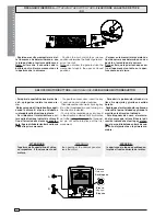
84 mm.

10

5 mm

.

50

 m

m

.

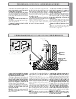
PRIMA DI INSTALLARE ... - 

BEFORE INSTALLING ...

 - ANTES DE INSTALAR EL AUTOMATISMO 

...

- Controllare che l'anta sia rigida e che le
ruote di scorrimento siano in buono stato
e adeguatamente ingrassate.
- La guida a terra dovrà essere ben fissata
al suolo, completamente in superficie in
tutta la sua lunghezza e priva di irregolari-
tà che possano ostacolare il movimento
del cancello.
- I pattini-guida superiori non devono cre-
are attriti.
- Prevedere una battuta d'arresto in aper-
tura e una in chiusura.
- Preparare il percorso dei cavi elettrici
come da impianto tipo.

- The gate must be sufficiently rigid and solid;
the wheels on which the gate slide must be in
perfect condition and adequately lubricated.
- The wheel guide must be firmly attached to
the ground, completely exposed, and without
any irregular sections which might hinder the
movement of the gate.
- The upper guide must allow for the correct
amount of play in order to guarantee smooth
and silent movement of the gate.
- Aperture and closure stops must be installed.
- The wiring must be routed as specified by
the control and safety requirements.

- La hoja de la puerta debe estar suficiente-
miente rigida y compacta; las ruedas de
deslizamiento deben estar perfecta y en-
grasadas adecuadamente.
- La guia de deslizamiento debe estar bien
fijada en el suelo, sobresaliendo a lo largo
de su entera longitud, sin irregularidades
(que podrian obstaculizar el movimiento
de la puerta).
- La guia superior debe tener el justo jue-
go con la puerta metálica (para garantizar
un movimiento regular y silencioso).
- Disponer un tope para apertura y el cie-
rre.
- Disponer un conducto para los cables
eléctricos que cumpla con las disposicio-
nes de mando y seguridad.

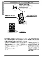
FISSAGGIO BASE MOTORE - 

MOTOR TO BASE ANCHORAGE

 - FIJACIÓN BASE MOTOR

- Inserire le viti nella piastra di ancoraggio
bloccandole con un dado, ed estrarre le
zanche preformate verso il basso.
- Predisporre, dimensionandola in base alle
misure del motoriduttore, una piazzola in
cemento (si consiglia di farla sporgere dal
terreno di circa 50 mm.) con annegata la
piastra di ancoraggio e relative zanche
sulla quale sara' fissato il gruppo.
- La base di fissaggio dovra' risultare per-
fettamente in bolla, pulita in tutte le sue
estremita', con il filetto delle viti comple-
tamente in superfice.
N.B.: Dalla stessa dovranno emergere i tubi
flessibili per il passaggio dei cavi di colle-
gamento elettrico.

- Install the screws in the anchor plate and
fasten them with a nut, then bend the pre-
formed clamps downwards.
- Construct a cement foundation that is large
enough to accomodate the gear motor (it is a
good idea to protrude 50 mm. from the ground).
When pouring the foundation, embed the gear
motor anchor plate and the relative clamps in
the cement.
- The anchor bolts should be embedded in the
concrete in the positions indicated; the drive
unit is then attached to this bots. The anchor
plate must be perfectly level and absolutly
clean; the bolts threads must be completly
exposed.
N.B.: The flexible tubes for the electrical wiring
must be embedded in the base and protude in
the correct position.

- Introducir los tornillos en la placa de an-
claje, bloqueándolos con una tuerca, y
doblar las palancas preformadas hacia aba-
jo (bloqueando de esa forma los tornillos).
- Preparar, dándole las dimensiones ade-
cuadas en función de las medidas del
motorreductor, una plataforma de cemen-
to (se aconseja dejarla sobresalir del sue-
lo aprox. 50 mm.) con la placa de enclaje
embedida y con las correspondientes va-
rillas, que permitrá la fijación del grupo.
- La base de fijación debe estar perfecta-
mente nivelada, limpia en todos sus extre-
mos, con la rosca de los tornillos
totalmente in superficie.
N.B.: De ésta deben sobresilar los tubos
flexibles para el paso de los cables para
las conexiones eléctricas.

Anta cancello

Gate wing

Puerta

Cremagliera

Rack-limit

Cremallera

Piastra di ancoraggio/Zanche

Fixing plate/ Anchor stays

Placa de fijaci

ón/arras de fijción

Cavi

Cable

Cables

Piazzola in cemento

Concrete base

Plataforma de cemento

Struttura fissa

Wall

Estructura fija

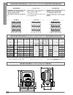
Summary of Contents for BK-BKE

Page 1: ...3 Ricevitore radio 4 Alette finecorsa 5 Cremagliera 6 Selettore a chiave 7 Lampeggiatore di movimento 8 Antenna di ricezione 9 Fotocellule di sicurezza 10 Colonnina per fotocellula 11 Fermo anta 1 BK unit 2 Control panel incorporated 3 Radio receiver 4 Limit switch tabs 5 Rack 6 Key operated selector switch 7 Flashing light indica ting door movement 8 Antenna 9 Safety photocells 10 Photocell colum...

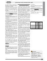
Page 2: ...ed with CAME control panel Empuje regulable obtenido mediante tablero de control CAME POTENZA POWER POTENCIA 380 W 310 W 480 W 440W 580 W 500 W ASSORBIMENTO CURRENT ABSORBENCIA 3 3A 5 6A 4 2A 8 A 5 1A 9 1A ALIMENTAZIONE POWER SUPPLY ALIMENTACION 230Va c 120Va c 230Va c 120Va c 230Va c 120Va c PESO WEIGHT PESO 18Kg 19 5Kg 21Kg MOTORIDUTTORE GEARMOTOR MOTORREDUCTOR BK BKE 1200 BK BKE1210 BK BKE 1800...

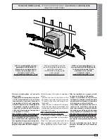
Page 3: ... dimensionandola in base alle misure del motoriduttore una piazzola in cemento si consiglia di farla sporgere dal terreno di circa 50 mm con annegata la piastra di ancoraggio e relative zanche sulla quale sara fissato il gruppo La base di fissaggio dovra risultare per fettamente in bolla pulita in tutte le sue estremita con il filetto delle viti comple tamente in superfice N B Dalla stessa dovrann...

Page 4: ...dini filettati in acciaio che permet tono la regolazione verticale e la mes sa in bolla le piastrine e i dadi di fissaggio che rendono solidale l aggancio del grup po alla base During the initial phase of installation the feet should protude by 5 10 mm in order to allow for alignment anchorage of the rack and further adjustments Perfect alignment with the guide rail is made possible by the paten t...

Page 5: ...ntil If the rack is already attached proceed direc tly to the adjustment of the rack pin ion coupling When the necessary adjustment have been completed fasten the unit in posi tion by tightening the two anchor bolts Fijar la cremallera en la puerta metáli ca como se indica a continuación Apoyar la cremallera en el piñón mo torreductor y deslizar manualmente la puerta metálica fijando la cremallera...

Page 6: ...o della stessa e senza for zare il perno trilobato rientrerà nella sua sede alla prima manovra To open the access door insert the key A push down and rotate clockwise Then release the ratio motor by using key B on the threelobed pin and turning it in the direction indicated To re lock the reduction gear turn key B in the direction indicated until it will move no further without forcing it the thre...

Page 7: ... dopo un intervento di stop totale o in mancanza di energia elettrica Apertura parziale Apertura del can cello per passaggio pedonale viene attivata collegandosi ai morsetti 2 3P ed è regolabile mediante trimmer AP PARZ Con questa funzione la chiu sura automatica varia nel seguente modo 1 Dip 12 in ON dopo un apertura par ziale il tempo di chiusura automatica è indipendente dalla regolazione del t...

Page 8: ...fety system and is deactivated after a STOP command or in case of power failure Partial opening Opening of the gate to allow for foot traffic activated by connecting to terminals 2 3P and ad justed with the AP PARZ trimmer With this function the automatic closing can vary in the following way 1 Dip 12 set to ON after a partial open ing the time for automatic closing func tions independently of the...

Page 9: ... sin embargo está subordinado a la inter vención de posibles accesorios de se guridad y se excluye después de una intervención de parada o en caso de falta de energía eléctrica Apertura parcial La apertura de la verja para el paso peatonal se activa conec tando los bornes 2 3P y puede ser re gulada por medio del trimmer AP PARZ Con dicha función el cierre automático se modifica de la siguiente man...

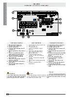
Page 10: ...use see p 8 3 2A accessories fuses 4 Socket AF radiofrequency board see p 20 5 24Vpower supplysignallingLED 6 Radio codesaveandlimit switch programmingbuttons 7 Functionselection dip switch 8 TrimmerAP PARZ Partialopening adjustment 9 TrimmerTCA automaticclosingtime adjustment 10 Radio codeandencoder programming LED 11 Encodermotherboard ZBKE motherboard Caution Before doing any connection or disc...

Page 11: ...lash on the control panel and the radio transmitter and the control push button will be deactivated Electricalconnectionsrequiredforsafe ty test function Photocell lamps and sensors must be connected as follows connect the photocell sensor across terminalsTS 10 Connectthephotocell lamp across terminals 10 11 see dia gram move dip switch 13 to ON which will activate the test function IMPORTANT When...

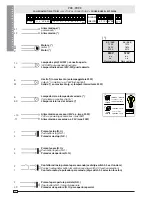
Page 12: ...n motion e g 25W flashing light Salida en movimento p ej lámpara intermitente 25W Lampada ciclo o lampada di cortesia Cycle lamp or courtesy light Lámpara ciclo luz de cortesía Alimentazione accessori 24V a c max 20W 24V a c powering accessories max 20W Alimentación accesoios a c 24V max 20W Pulsantestop N C Pushbutton stop N C Pulsador de stop N C Pulsanteapre N O Pushbuttonopens N O Pulsador de ...

Page 13: ...op parziale selezionare dip 8 in OFF 9 in ON Partial stop contact N C Set Dip 8 to OFF 9 to ON Contacto N C de parada parcial seleccione el dip 8 en OFF 9 en ON Collegamentoantenna Antennaconnection Conexiónantena Uscita contatto N O Portata contatto 5A a 24V d c Contact output N O Resistive load 5A 24V d c Salida contacto N O Carga resistiva 5A a 24V d c Uscita per comando di n 2 motori abbinati ...

Page 14: ...block Gruppo motore finecorsa già colle gati per montaggio a sinistra vista interna Per eventuale montaggio a destra invertire FA FC dei finecorsa sulla morsettiera invertirelefasiU Vdelmotoresulla morsettiera Grupomotorfindecarrerayaconec tados para el montaje a la izquierda vista interior Para el eventual mon taje a la derecha invertirFA FCdelosfinesdecarre ra en el cuadro de bornes invertirlasf...

Page 15: ...zione inizia a lampeggia re 1 Portareilcancelloinfinecorsa chiude premereiltasto CHIUDE il led rimane acceso finchè si mantie ne premuto il tasto 2 Procedere portando il cancello a fi necorsa apre e premere il tasto APRE 3 RiposizionareilDip switch15inOFF 4 N B Infasediprogrammazionefine corsa apre se premendo il tasto APRE illedrimanespento inverti re le fasi del motore ed Encoder come illustrato...

Page 16: ...is selected enabled 4 OFF disabled 5 ON Pre flashing opening and closing en abled 5 OFF disabled 6 ON Function obstacle detection device enabled 6 OFF disabled 7 OFF Function re opening in closing phase connect the safety device on termi nals 2 C1 enabled 7 ON disabled 8 OFF 9 OFF Function of re closing while opening connect the safety device on terminals 2 CX enabled 8 OFF 9 ON Partial stop funct...

Page 17: ... enabled 13 ON Activates safety test that checks the photocells proper operation see pag 11 enabled 13 OFF disabled 14 OFF Master function deactivated to active only for coupled connection see page 19 15 ON Function spare limit switch program ming onlyforZBKE pag 15 enabled 15 OFF disabled 16 ON Courtesy light function enabled 16 OFF disabled 17 ON Lamp cycle function enabled 17 OFF disabled 18 No...

Page 18: ...ly on the MASTER board Fig 2 Wire the electrical connections and the normally used selections only on the MASTER terminal board Fig 3 Wire the electrical connections be tweentheterminalboards asshownin the figure A and make sure that the automatic closing function is enabled for the master motor and disabled for 2nd motor Make sure that all the dip switches on the board of the 2nd motor are OFF ex...

Page 19: ...tiera motore master Master motor terminal block Cuadro de bornes motor master Chiusura automatica attivata Automatic closure enabled Cierre automático activado Chiusura automatica disattivata Automatic closure disabled Cierre automático desactivado Morsettiera 2 motore Motor 2 terminal block Cuadro de bornes 2 motor SETTAGGIO OBBLIGATORIO OBLIGATORY SETTING REGULACION OBLIGATORIA FUNZIONI FUNCTION...

Page 20: ...t card AF43S as shown on the sheet Para transmisores con frecuencia 433 92 AM serie TOP y serie TAM es necesario en la tarjeta corespon diente AF43S colocar el jumper como se indica La schedina AF deve essere inserita OBBLIGATORIAMENTE in assenza di ten sione perché la scheda madre la ricono sce solo quando viene alimentata The AF board should ALWAYS be in serted when the power is off because the ...

Page 21: ...istrare il codice al decimo impulso un doppio suono confermerà l avvenuta registrazione Press P1 or P2 in sequence in order to regis ter the code at the tenth pulse a double beep will confirm that registration has occurred oprimir repetidamente P1 ó P2 para registrar el código con el décimo impulso un doble sonido señalará que el registro se ha efec tuado 2 codice codice codice 1 codice codice cod...

Page 22: ...3 CH4 P1 CH1 CH2 CH3 CH4 1 2 3 4 1 2 3 4 1 2 3 4 1 2 3 4 1 2 3 4 1 2 3 4 1 2 3 4 1 2 3 4 vedi istruzioni su confezione see instructions on pack ver instrucciones en el embalaje T432S T432SA T434MA T434M T314M impostare solo il codice set code only plantear sólo el código P1 CH1 P2 CH2 P3 CH3 P4 CH4 1 2 3 4 5 6 7 8 9 10 C P1 P2 P3 P4 CODIFICA TRASMETTITORI TRANSMITTER ENCODING CODIFICACIÓN TRANSMIS...

Page 23: ...ode figure 1 Perform the same procedure with the CH2 key associating it with another transmitter key figure 2 CH1 Channel for direct control of one function performed by the control unit on the gear motor open only open close reverse or open stop close stop depending on the position of dip switches 2 and 3 CH2 Channel for direct control of an accessory connected across B1 B2 N B If you wish to cha...

Page 24: ...GNETIC COMPATIBILITY EN 50082 1 AND 2 ELECTROMAGNETIC COMPATIBILITY IMPORTANT CAUTION It is forbidden to market use product s that are the subject of this declaration before completing and or incorporating them in total compliance with the provisions of Machinery Directive 98 37 CE Signatures of the Representatives Specific technical documentation on the products is available on request Date of th...

Reviews: