background image

5.1 Preliminary checks


Before actually installing the gate operator, your are required to:

• Check that the leaf is rigid and compact and that the rollers are in good working order and properly greased;

• The gate track must be firmly set into the ground, above ground along its entire length and free of any foreign objects (debris) 
that may hamper the gate’s movement;

• The top non-pinch rollers must not cause any friction;

• See to installing physical stops at fully-opened and fully-closed positions and the power supply line trench as per the standard 
installation;

• Make sure that the spot were the operator is mounted is located in an area that is protects it from any impacts, and that the 
mounting surface be solid; 

• See to installing a suitable all-pole disconnector switch, with power isolation contacts more than 3mm apart from each 
other;

•      Connections inside of the casing made to provide continuity to the protection circuit are allowed, as long as they have 
additional isolation compared to other internal conductive parts; 

• Set up suitable tubing and trenching to allow for electrical cables to pass, making sure they are free from any potential mecha-
nical damage.


Only expert, qualified personnel must carry out the installation, in full compliance with the applicable law. 

5 Installation

5.2 Tools and materials

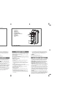
Make sure you have all the tools and materials handy, to carry out the installation in total safety, according to the laws in-for-
ce. Below is a drawing of the tools you will need to install the operator.

N.B.:  An evaluation of the size of the cables with lengths other than the data in the table must be made based on the effective 
absorption of the connected devices, according to the instructions indicated by the CEI EN 60204-1 standards.
For connections that require several loads on the same line (sequential), the size given on the table must be re-evaluated based 
on actual absorption and distances.

5.3 Cable list and minimun thickness

Connections

Type of cable

Length of cable 1 < 10 m Length of cable 10 < 20 m  Length of cable 20 < 30 m

120V-230V 2F power supply

FROR CEI 

20-22 

CEI EN 

50267-2-1

3G x 1,5 mm

2

3G x 2,5 mm

2

3G x 4 mm

2

230V flashing lamp

2 x 0,5 mm

2

2 x 1 mm

2

2 x 1,5 mm

2

Photoelectric cells TX

2 x 0,5 mm

2

2 x 0.5 mm

2

2 x 0,5 mm

2

Photoelectric cells RX

4 x 0,5 mm

2

4 x 0,5 mm

2

4 x 0,5 mm

2

24V power supply accessory

2 x 0,5 mm

2

2 x 0,5 mm

2

2 x 1 mm

2

Control button

2 x 0,5 mm

2

2 x 0,5 mm

2

2 x 0,5 mm

2

Antenna connection

RG58

max. 50 m


4


A

ll t

h

e d

at

a a

n

d i

n

fo

rm

at

io

n c

o

n

ta

in

ed h

er

ei

n

 i

s c

o

n

si

d

er

ed

 s

u

b

je

ct to c

h

an

g

e a

t a

n

y t

im

e a

n

d a

t o

u

r d

is

cr

et

io

n

ENGLISH

Summary of Contents for BK 2200

Page 1: ...AUTOMATION FOR SLIDING GATES BK INSTALLATION MANUAL BK 800 1200 1800 2200 BKE 1200 1800 2200...

Page 2: ...cessories are CAME originals this is a guarantee that also makes the system easy to set up and upkeep 4 Description 2 1 Destination 1 Legend This symbol indicates sections to be read with particular c...

Page 3: ...ES 1 R001 Cylinder lock with DIN keys 2 BSF Braking device 3 BRC Cable winding device 4 B4353 Chain transmission device 5 CCT Simple 1 2 chain 6 CGIU 1 2 chain joint 7 CGZ Galvanized steel 22 x 22 mod...

Page 4: ...nnel must carry out the installation in full compliance with the applicable law 5 Installation 5 2 Tools and materials Make sure you have all the tools and materials handy to carry out the installatio...

Page 5: ...lamps downwards Construct a cement foundation that is large enough to accomodate the gear motor it is a good idea to protrude 50 mm from the ground When pouring the foundation embed the gear motor anc...

Page 6: ...ble by the paten ted built in regulation system which consists of slots for horizontal adjustment threaded steel feet for vertical adjustment and levelling plates and bolts for anchorage to the base 5...

Page 7: ...icated To re lock the reduction gear turn key B in the direction indicated until it will move no further without forcing it the three sided pin will settle into place at the first movement 5 7 Attachi...

Page 8: ...the 24V accessories must not exceed 20W The operating time interval is fixed at 150 seconds The photocells can be connected and set to re open during the closing phase re open during the opening phase...

Page 9: ...Connection for gear motor limit switch or encoder RED Invert the phases of the gear motor U V On the BK series invert wires FA FC On the BKE series invert the wires of the shielded cable BLACK Connect...

Page 10: ...d Courtesy lamp Contact output 230V 60 V max Auxiliary connection for suitably positioned external lamp to increase lighting of the steering area It remain lit for a fixed time of 5 minutes and 30 sec...

Page 11: ...ds If in motion the gate leaf stops and automatic closing is consequently triggered DIP 8 OFF DIP 9 ON N C contact for re closing during opening phase Input for safety devices such as photocells sensi...

Page 12: ...stand by time in the opening phase a k a pause time When the time elapses the gate automatically closes The pause time can be adjusted from 1 second to 150 seconds PAR OP Trimmer Partial opening Adjus...

Page 13: ...version of movement direction until the gate is fully closed insert safety device into terminal 2 CX 8 OFF 9 ON Partial stop The gate stops completely when moving consequently triggering the automatic...

Page 14: ...s long as the button is kept pressed N B By pressing the OPEN button during this procedure the led indicator does not turn on invert the phases of the motor U V and of the Encoder see para 6 3 electri...

Page 15: ...on dip switch 11 to the ON position to place it into a slave state N B Make sure that the radio frequency board is inserted only into the Master board A B 8 Connection of two coupled gear motors with...

Page 16: ...on the command board paragraph 9 3 Radio board AF Motherboard TOP TAM 2 The AF board must ALWAYS be inserted into the coupling ref point 5 page 8 when the power is off because the motherboard only rec...

Page 17: ...TFM T132 T134 T138 T152 T154 T158 CAME TOP SERIES 17 All the data and information contained herein is considered subject to change at any time and at our discretion ENGLISH set the code to dip switch...

Page 18: ...4 disinserire jumper J 0 0 0 0 TOP T262M T302M FIG A FIG B P1 CH1 P2 CH2 P1 CH1 P2 CH3 P1 CH3 P2 CH2 P1 CH1 P2 CH4 P1 CH3 P2 CH4 TOP QUARTZ SERIES Press P1 or P2 in sequence in order to register the c...

Page 19: ...nd at our discretion ENGLISH TCH 4024 TCH 4048 AT01 AT02 AT04 CAME 0 0 0 0 T264M T304M 0 0 0 0 0 0 T2622M T3022M P1 CH1 P2 CH2 P3 CH3 P4 CH4 1 Code P1 CH1 P2 CH2 2 Code P3 CH1 P4 CH2 ATOMO SERIES TOUC...

Page 20: ...Memorizing the code on the command board CH1 Channel for direct commands to a function of the ratiomotor control unit open only open clo se invert direction commands or the open stop close stop comman...

Page 21: ...ecycled by disposing of in specific re cyclable material collection bins and disposal in authorized centres Other components electrical boards remote control batteries etc however may contain pollutin...

Page 22: ...Cod 119BS04 ver 4 0 01 06 CAME CANCELLI AUTOMATICI...

Reviews: