background image

P

ag. 

14

 - Manuale 

FA01610-IT

  - 08/2021 - © C

AME S.p.A. - I contenuti del manuale sono da ritenersi suscettibili di modifica in qualsiasi momento senza obb

ligo di pr

eav

viso. - Istruzioni originali

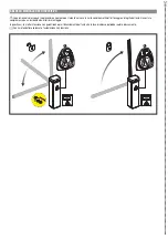
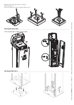
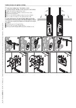
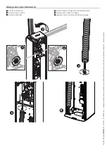
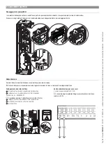
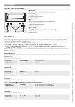
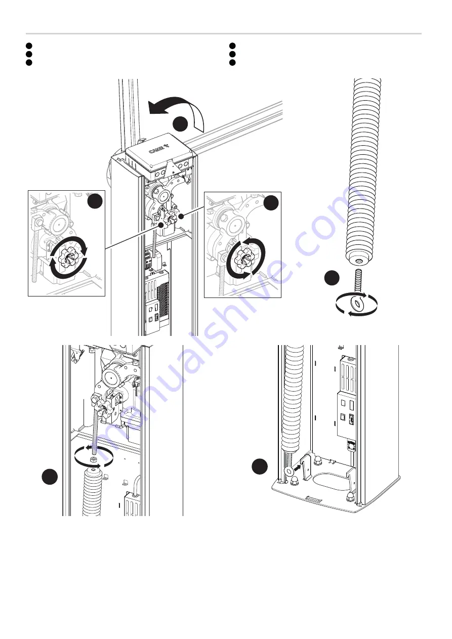
Montaggio della molla di bilanciamento

1

 Sbloccare il motoriduttore.

2

 Posizionare l'asta in verticale

3

 Bloccare il motoriduttore

4

 Avvitare il tirante a occhiello alla parte inferiore della molla

5

 Avvitare la molla al perno di ancoraggio.

6

 Agganciare il tirante a occhiello alla staffa di ancoraggio

3

2

1

4

5

6

Summary of Contents for 803BB-0120

Page 1: ...Barriere stradali automatiche GARD PX Brushless GPX40MGP GPX40MGS GPX40MGC GPX40MXP GPX40MCP MANUALE DI INSTALLAZIONE FA01610M04 IT Italiano EN English FR Fran ais RU P...

Page 2: ...ondizioni ottimali di fissaggio e integrit dell asta siano state compromessa da un incidente o da errori di montaggio In questi casi le molle in tensione non garantiscono pi il bilanciamento dell asta...

Page 3: ...categoria di sovratensione III Delimitare adeguatamente l intero sito per evitare l accesso da parte di persone non autorizzate in particolare minori e bambini Nel caso di movimentazione manuale preve...

Page 4: ...dell imballo cartone plastiche etc sono assimilabili ai rifiuti solidi urbani e possono essere smaltiti senza alcuna difficolt semplicemente effettuando la raccolta differenziata per il riciclaggio Pr...

Page 5: ...era automatica con motoriduttore irreversibile e motore brushless armadio in AISI 430 verniciato Fornita completa di 009SMA e di un interfaccia per il collegamento diretto ad una colonnina ingresso us...

Page 6: ...chio 7 Manopola di sblocco blocco dell asta 8 Quadro di comando 9 Fermo meccanico per il registro dell asta 10 Contatti ausiliari di stato 11 Perno di ancoraggio della molla 12 Scheda I O RS485 13 Mod...

Page 7: ...di sicurezza motoriduttore sbloccato contatto NC 15 Morsettiera per il collegamento dei micro di finecorsa contatto NC 16 Morsettiera associata al connettore RSE_2 per collegamento CRP scheda IO 485 o...

Page 8: ...45 IEC 57 Per posa in ambiente interno utilizzare cavi con propriet almeno equivalenti a quelli di tipo H05VV F designazione alla 60227 IEC 53 Qualora i cavi abbiano lunghezza diversa rispetto a quant...

Page 9: ...io Operazioni preliminari Se la pavimentazione presente non consente un fissaggio solido e stabile del dispositivo preparare una piazzola di cemento Fare lo scavo per la cassa matta Preparare i tubi c...

Page 10: ...momento senza obbligo di preavviso Istruzioni originali Riempire di terra lo scavo attorno al blocco di cemento Togliere i dadi dalle viti Inserire i cavi elettrici nei tubi fino a farli uscire di 15...

Page 11: ...uotando la manopola in senso orario 3 Ruotare il braccio leva di 90 4 Bloccare il motoriduttore ruotando la manopola in senso antiorario 5 Fissare il perno di ancoraggio al foro opposto del braccio le...

Page 12: ...originali Montaggio dell asta Montare il copri attacco dell asta sulla piastra di fissaggio Lasciare le viti leggermente allentate per facilitare il successivo inserimento dell asta Inserire il rinfo...

Page 13: ...combaciare con il tappo terminale 3 Inserire il tappo terminale di gomma nell apposita sede 6 Inserire il tappo terminale del profilo di gomma nella scanalatura del tappo di chiusura dell asta Fissar...

Page 14: ...di preavviso Istruzioni originali Montaggio della molla di bilanciamento 1 Sbloccare il motoriduttore 2 Posizionare l asta in verticale 3 Bloccare il motoriduttore 4 Avvitare il tirante a occhiello al...

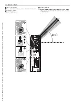
Page 15: ...asta 1 Sbloccare il motoriduttore 2 Ruotare manualmente la molla per aumentare o diminuire la trazione L asta deve stabilizzarsi a 45 gradi 3 Fissare il controdado Posizionare l asta in verticale 4 Bl...

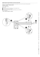
Page 16: ...e quando in posizione di chiusura e a circa 89 quando in posizione di apertura Correggere la posizione orizzontale dell asta Sbloccare il motoriduttore Aprire lo sportello di ispezione Abbassare l ast...

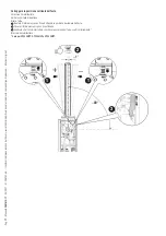
Page 17: ...zione verticale dell asta Sbloccare il motoriduttore Aprire lo sportello di ispezione Alzare l asta 1 Ruotare il fermo meccanico fino ad ottenere la posizione desiderata dell asta 2 Fissare il fermo m...

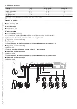
Page 18: ...one assicurarsi di operare fuori tensione Prima di intervenire sul quadro di comando togliere la tensione di linea e se presenti scollegare le batterie Collegamento alla rete elettrica 1 Pulsante per...

Page 19: ...NC Arresta l asta ed esclude l eventuale chiusura automatica Usare un dispositivo di comando per riprendere il movimento Se il contatto non viene utilizzato deve essere disattivato in fase di programm...

Page 20: ...aperto o che il motoriduttore sbloccato o che l asta caduta A B GND A B GND R G B 2 10 S1GND A B 11 E1 E6 TS 1 2 3 3P 4 5 7 2 CX CY CZ FA FC FCA CM1 FCC CM2 MOTOR BLOCK 1 2 3 4 Dispositivi di sicurez...

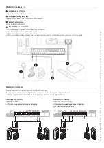
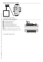
Page 21: ...azione asta aperta 3 Uscita contatto segnalazione asta chiusa 4 Uscita contatto segnalazione caduta asta 5 Uscita contatto segnalazione sportello di ispezione aperto 6 Uscita contatto segnalazione mot...

Page 22: ...he appare a display Dopo aver dato tensione all impianto la prima manovra sempre in apertura attendere il completamento della manovra Premere immediatamente il tasto ESC o il pulsante di STOP se si ri...

Page 23: ...ssocia una funzione all ingresso CX Configurazione Sicurezze filari Ingresso CX Disattivato Default C1 Riapertura durante la chiusura Fotocellule C4 Attesa ostacolo Fotocellule C5 Chiusura immediata a...

Page 24: ...motore fermo Con la funzione attiva l asta rimane ferma se i dispositivi di sicurezza rilevano un ostacolo La funzione ha effetto con asta chiusa asta aperta o dopo uno stop totale Configurazione Sicu...

Page 25: ...ica Imposta il tempo che deve trascorrere prima che si attivi la chiusura automatica una volta che stato raggiunto il punto di finecorsa in apertura La funzione non si attiva nel caso in cui interveng...

Page 26: ...gurazione Comunicazione RSE Indirizzo CRP da 1 a 254 Velocit RSE1 Imposta la velocit di comunicazione del sistema di connessione remota sulla porta RSE1 Configurazione Comunicazione RSE Velocit RSE1 4...

Page 27: ...ione pu essere svolta mediante un trasmettitore o altro dispositivo di comando Le schede che gestiscono i dispositivi di comando AF R700 R800 devono essere innestate nei connettori Gestione utenti Nuo...

Page 28: ...stione utenti Self Learning Rolling Disattivato Attivato Cambio modalit Cambia la funzione assegnata ad un determinato utente L operazione pu essere svolta anche inviando un comando dal dispositivo as...

Page 29: ...oni relative alla taratura della corsa Informazioni Reset parametri Confermi NO Confermi SI Lista errori Visualizza gli ultimi 8 errori rilevati La lista errori pu essere cancellata Informazioni Lista...

Page 30: ...ve una delle temporizzazioni salvate Gestione timer Rimuovi timer Usare le frecce per scegliere la temporizzazione che si desidera rimuovere 0 Apertura P Apertura parziale Premere ENTER per confermare...

Page 31: ...chiavetta USB nella porta USB 2 Premere il pulsante Enter per accedere alla programmazione 3 Usare le frecce per scegliere la funzione desiderata Le funzioni vengono visualizzate solo quando viene in...

Page 32: ...32 Manuale FA01610 IT 08 2021 CAME S p A I contenuti del manuale sono da ritenersi suscettibili di modifica in qualsiasi momento senza obbligo di preavviso Istruzioni originali OPERAZIONI FINALI 4 3...

Page 33: ...come MASTER A B GND A B GND 1 2 3 3P 4 5 7 2 CX CY CZ FCA CM1 FCC CM2 RSE A B GND A B GND 1 2 3 3P 4 5 7 2 CX CY CZ FCA CM1 FCC CM2 RSE UTP CAT 5 max 1000 m Programmazione Tutte le operazioni di prog...

Page 34: ...spositivi e degli accessori vedere capitolo COLLEGAMENTI ELETTRICI I dispositivi di comando e di sicurezza vanno collegati su entrambe le schede elettroniche A B GND A B GND 1 2 3 3P 4 5 7 2 CX CY CZ...

Page 35: ...contenuti del manuale sono da ritenersi suscettibili di modifica in qualsiasi momento senza obbligo di preavviso Istruzioni originali 2 Comando SOLO APRE 2 3 sulla barriera B 3 Comando APRE CHIUDE 2 7...

Page 36: ...ioni relative alla corretta installazione e alle regolazioni consultare il manuale di installazione del prodotto Per le informazioni relative alla scelta del prodotto e degli accessori consultare il c...

Page 37: ...Nr massimo ostacoli in chiusura Superato il numero massimo di ostacoli rilevati consecutivamente Nr massimo ostacoli in apertura Superato il numero massimo di ostacoli rilevati consecutivamente Errore...

Page 38: ...Pag 38 Manuale FA01610 IT 08 2021 CAME S p A I contenuti del manuale sono da ritenersi suscettibili di modifica in qualsiasi momento senza obbligo di preavviso Istruzioni originali...

Page 39: ...Pag 39 Manuale FA01610 IT 08 2021 CAME S p A I contenuti del manuale sono da ritenersi suscettibili di modifica in qualsiasi momento senza obbligo di preavviso Istruzioni originali...

Page 40: ...I contenuti del manuale sono da ritenersi suscettibili di modifica in qualsiasi momento senza obbligo di preavviso Istruzioni originali CAME S p A Via Martiri della Libert 15 31030 Dosson di Casier Tr...

Page 41: ...Automatic road barriers GARD PX Brushless GPX40MGP GPX40MGS GPX40MGC GPX40MXP GPX40MCP INSTALLATION MANUAL FA01610 EN EN English...

Page 42: ...as been damaged or if the boom is no longer intact as the result of an accident or installation error In these cases the tensioned springs no longer guarantee that the boom is balanced The boom may su...

Page 43: ...th the installation rules It should completely cut off the power supply according to category III surcharge conditions Demarcate the entire site properly to prevent unauthorised personnel from enterin...

Page 44: ...uidelines DISPOSING OF THE PACKAGING The packaging materials cardboard plastic etc can be disposed of easily as solid urban waste separated for recycling Before dismantling and disposing of the produc...

Page 45: ...ersible gearmotor and brushless motor painted AISI 430 steel cabinet Supplied complete with 009SMA and an interface for direct connection to an entrance exit post for PKE and PKM parking systems Inten...

Page 46: ...hatch 6 Cover 7 Boom release lock knob 8 Control panel 9 Mechanical stop for the boom adjustment 10 Auxiliary status contacts 11 Spring anchoring pin 12 I O board RS485 13 SMA module 14 Auxiliary 15...

Page 47: ...C contact 15 Terminal boards for connecting micro limit switches NC contact 16 Terminal board associated with the RSE_2 connector for CRP connection IO 485 card or Modbus RTU interface 17 Terminal boa...

Page 48: ...lent to those of type H05RN F with designation 60245 IEC 57 For installation in an indoor environment use cables with properties at least equivalent to those of type H05VV F designation to 60227 IEC 5...

Page 49: ...ened in place Preliminary operations If the flooring does not allow the device to be fastened in a solid and stable way lay a cement slab Dig a hole for the foundation frame Set up the corrugated tube...

Page 50: ...notice Translation of the original instructions Fill the hole with soil around the concrete block Remove the nuts from the screws Thread the electrical cables into the tubes so that they protrude by a...

Page 51: ...pin from the lever arm 2 Release the gearmotor turning the knob clockwise 3 Turn the lever arm by 90 4 Lock the gearmotor turning the knob anticlockwise 5 Fasten the anchoring pin to the opposite hol...

Page 52: ...nal instructions Boom installation Install the boom attachment cover on the anchoring plate Leave the screws slightly loose for easier fitting of the boom later Insert the reinforcement inside the boo...

Page 53: ...ve aligning it with the end cap 3 Fit the rubber end cap in position 6 Insert the rubber profile end cap into the groove in the boom closing cap Use the screws to fasten the boom end cap 7 Fit the ant...

Page 54: ...tice Translation of the original instructions Assembling the balance spring 1 Release the gearmotor 2 Position the boom vertically 3 Lock the gearmotor 4 Tighten the eyelet tie rod to the lower part o...

Page 55: ...Balancing the boom 1 Release the gearmotor 2 Manually turn the spring to increase or reduce the traction The boom should stabilise at 45 3 Fasten the locknut Position the boom vertically 4 Lock the ge...

Page 56: ...road surface when it is in the closed position and at about 89 when it is in the open position Correct the boom s horizontal position Release the gearmotor Open the inspection hatch Lower the boom 1...

Page 57: ...ct the boom s vertical position Release the gearmotor Open the inspection hatch Raise the boom 1 Turn the mechanical stop until you reach the desired boom position 2 Fasten the mechanical stop with a...

Page 58: ...disconnected during all installation procedures Before working on the control panel disconnect the mains power supply and remove the batteries if any Connecting to the electrical network 1 Button for...

Page 59: ...r switch 4 Keypad selector 5 STOP button NC contact This stops the boom and excludes automatic closing Use a control device to resume movement If the contact is not used it must be deactivated during...

Page 60: ...the gearmotor is released or the boom has dropped away A B GND A B GND R G B 2 10 S1GND A B 11 E1 E6 TS 1 2 3 3P 4 5 7 2 CX CY CZ FA FC FCA CM1 FCC CM2 MOTOR BLOCK 1 2 3 4 Safety devices Connect the s...

Page 61: ...Contact output indicating open boom 3 Contact output indicating closed boom 4 Contact output indicating boom drop away 5 Contact output indicating inspection hatch open 6 Contact output indicating gea...

Page 62: ...isplay After powering up the system the first manoeuvre is always to open the gate Wait for the manoeuvre to be completed Press the ESC button or STOP button immediately in the event of any faults mal...

Page 63: ...input Configuration Wired safety devices CX input Deactivated Default C1 Reopen while closing photocells C4 Obstacle standby photocells C5 Immediate closure at the travel end during opening C7 Reopen...

Page 64: ...st with motor stopped With the function active the boom remains stopped if the safety devices detect an obstacle The function activates with closed boom open boom or after a complete stop Configuratio...

Page 65: ...ic closure Set the time before automatic closure is activated once the opening travel end point has been reached The function does not work if any of the safety devices are triggered when an obstacle...

Page 66: ...rators connected via CRP Configuration RSE communication CRP address 1 to 254 RSE1 speed Set the remote connection system communication speed on the RSE1 port Configuration RSE communication RSE1 spee...

Page 67: ...on can be carried out by using a transmitter or another control device The boards that manage the control devices AF R700 R800 must be inserted into the connectors Manage users New user Step by step S...

Page 68: ...users Self Learning Rolling Off On Change mode Change the function assigned to a specific user This operation can also be carried out by sending a command from the device associated to the user Manage...

Page 69: ...h and the settings related to travel calibration Information Parameter reset Confirm NO Confirm YES Errors list View the last 8 errors detected The error list can be deleted Information Errors list Us...

Page 70: ...timer Removes one of the saved timings Timer management Remove timer Use the arrows to choose the timing to be removed 0 Opening P Partial opening Press ENTER to confirm Commands Run certain barrier c...

Page 71: ...nu view Import export data 1 Insert a USB flash drive into the USB port 2 Press the Enter button to access programming 3 Use the arrows to choose the desired function The functions are displayed only...

Page 72: ...Page 32 Manual FA01610 EN 08 2021 CAME S p A The contents of this manual may be changed at any time and without notice Translation of the original instructions FINAL OPERATIONS 4 3 2 1...

Page 73: ...o the control board which will be set as the MASTER A B GND A B GND 1 2 3 3P 4 5 7 2 CX CY CZ FCA CM1 FCC CM2 RSE A B GND A B GND 1 2 3 3P 4 5 7 2 CX CY CZ FCA CM1 FCC CM2 RSE UTP CAT 5 max 1000 m Pro...

Page 74: ...the devices and accessories please see the ELECTRICAL CONNECTIONS section The control and safety devices must be connected on both electronic boards A B GND A B GND 1 2 3 3P 4 5 7 2 CX CY CZ FCA CM1 F...

Page 75: ...21 CAME S p A The contents of this manual may be changed at any time and without notice Translation of the original instructions 2 ONLY OPEN command 2 3 on barrier B 3 OPEN CLOSE command 2 7 on barrie...

Page 76: ...spring and remove the boom For information on correct installation and adjustments please see the product installation manual For information on choosing products and accessories please see our produ...

Page 77: ...imum number of closing obstacles The maximum number of obstacles detected consecutively has been exceeded Maximum number of opening obstacles The maximum number of obstacles detected consecutively has...

Page 78: ...Page 38 Manual FA01610 EN 08 2021 CAME S p A The contents of this manual may be changed at any time and without notice Translation of the original instructions...

Page 79: ...Page 39 Manual FA01610 EN 08 2021 CAME S p A The contents of this manual may be changed at any time and without notice Translation of the original instructions...

Page 80: ...AME S p A The contents of this manual may be changed at any time and without notice Translation of the original instructions CAME S p A Via Martiri della Libert 15 31030 Dosson di Casier Treviso Italy...

Page 81: ...Barri res automatiques GARD PX Brushless GPX40MGP GPX40MGS GPX40MGC GPX40MXP GPX40MCP MANUEL D INSTALLATION FA01610 FR FR Fran ais...

Page 82: ...optimales de fixation et d int grit de la lisse ont t compromises par un accident ou des erreurs de montage Dans ces cas les ressorts tendus ne garantissent plus l quilibrage de la lisse qui en phase...

Page 83: ...de d connexion omnipolaire sp cifique pour le sectionnement total en cas de surtension cat gorie III D limiter soigneusement toute la zone afin d en viter l acc s aux personnes non autoris es notamme...

Page 84: ...rton plastiques etc sont assimilables aux d chets urbains solides et peuvent tre limin s sans aucune difficult en proc dant tout simplement la collecte diff renci e pour le recyclage Avant d effectuer...

Page 85: ...vec motor ducteur irr versible et moteur sans balai f t en AISI 430 peint Fournie avec 009SMA et une interface pour la connexion directe une borne d entr e sortie de syst mes de stationnement type PKE...

Page 86: ...llage verrouillage de la lisse 8 Armoire de commande 9 But e m canique pour le r glage de la lisse 10 Contacts auxiliaires d tat 11 Goujon de fixation du ressort 12 Carte E S RS485 13 Module SMA 14 Bl...

Page 87: ...n du micro interrupteur de s curit motor ducteur d bloqu contact NF 15 Bornier de connexion des micro interrupteurs de fin de course contact NF 16 Bornier associ au connecteur RSE_2 pour connexion CRP...

Page 88: ...F avec d signation 60245 IEC 57 Pour la pose en int rieur utiliser des c bles aux propri t s au moins quivalentes celles des c bles H05VV F avec d signation 60227 IEC 53 Si la longueur des c bles ne...

Page 89: ...pas s y appuyer tant que la fixation n a pas t compl t e Op rations pr liminaires Si le sol ne permet pas une fixation solide et stable du dispositif pr parer un bloc de ciment Creuser la fosse pour l...

Page 90: ...aucun pr avis Traduction des instructions originales Remplir de terre le trou autour du bloc de ciment Enlever les crous des vis Introduire les c bles lectriques dans les gaines jusqu ce qu ils sorten...

Page 91: ...uer le motor ducteur en tournant la poign e dans le sens horaire 3 Tourner le bras levier de 90 4 Bloquer le motor ducteur en tournant la poign e dans le sens anti horaire 5 Fixer le goujon de fixatio...

Page 92: ...ons originales Montage de la lisse Installer le cache plaque de fixation de la lisse sur la plaque de fixation Ne pas serrer les vis fond de mani re faciliter ensuite l introduction de la lisse Introd...

Page 93: ...la rainure sp cifique en le faisant co ncider avec l embout 3 Introduire l embout en caoutchouc dans le logement 6 Introduire l embout du profil en caoutchouc dans la rainure du couvercle de la lisse...

Page 94: ...n pr avis Traduction des instructions originales Montage du ressort d quilibrage 1 D bloquer le motor ducteur 2 Positionner la lisse la verticale 3 Embrayer le motor ducteur 4 Visser le tirant illet s...

Page 95: ...loquer le motor ducteur 2 Tourner manuellement le ressort pour augmenter ou r duire la traction La lisse doit se stabiliser 45 degr s 3 Fixer le contre crou Positionner la lisse la verticale 4 Embraye...

Page 96: ...surface de la route en position de fermeture et environ 89 en position d ouverture Corriger la position horizontale de la lisse D bloquer le motor ducteur Ouvrir la porte de visite Baisser la lisse 1...

Page 97: ...verticale de la lisse D bloquer le motor ducteur Ouvrir la porte de visite Lever la lisse 1 Tourner la but e m canique jusqu obtenir la position souhait e de la lisse 2 Fixer la but e m canique l aide...

Page 98: ...nstallation que l automatisme est bien hors tension Avant d intervenir sur l armoire de commande mettre hors tension et d connecter les ventuelles batteries Connexion au r seau lectrique 1 Bouton pour...

Page 99: ...d sactive l ventuelle fermeture automatique Utiliser un dispositif de commande pour reprendre le mouvement Si le contact n est pas utilis il doit tre d sactiv pendant la programmation 6 Dispositif de...

Page 100: ...ite est ouverte ou que le motor ducteur est d bray ou que la lisse est tomb e A B GND A B GND R G B 2 10 S1GND A B 11 E1 E6 TS 1 2 3 3P 4 5 7 2 CX CY CZ FA FC FCA CM1 FCC CM2 MOTOR BLOCK 1 2 3 4 Dispo...

Page 101: ...sation lisse ouverte 3 Sortie contact signalisation lisse ferm e 4 Sortie contact signalisation chute lisse 5 Sortie contact signalisation porte de visite ouverte 6 Sortie contact signalisation motor...

Page 102: ...sion la premi re man uvre a toujours lieu en ouverture attendre l ex cution compl te de la man uvre Appuyer imm diatement sur la touche ESC ou le bouton d ARR T STOP en cas d anomalies mauvais fonctio...

Page 103: ...Entr e CX Associe une fonction l entr e CX Configuration S curit s filaires Entr e CX D sactiv par d faut C1 R ouverture durant la fermeture Photocellules C4 Attente obstacle Photocellules C5 Fermetu...

Page 104: ...a fonction est activ e la lisse reste immobile si les dispositifs de s curit d tectent un obstacle La fonction est activ e avec lisse ferm e lisse ouverte ou apr s un arr t total Configuration S curit...

Page 105: ...Fermeture automatique Configure le temps devant s couler avant que la fermeture automatique ne soit activ e une fois que le point de fin de course a t atteint en phase d ouverture La fonction n est pa...

Page 106: ...uration Communication RSE Adresse CRP de 1 254 Vitesse RSE1 Configure la vitesse de communication du syst me de connexion distance sur le port RSE1 Configuration Communication RSE Vitesse RSE1 4800 bp...

Page 107: ...tre dispositif de commande Les cartes qui g rent les dispositifs de commande AF R700 R800 doivent tre enfich es dans les connecteurs Gestion utilisateurs Nouvel Utilisateur Pas pas S quentielle Ouvert...

Page 108: ...angement de modalit Modifie la fonction attribu e un utilisateur bien pr cis Il est galement possible d effectuer cette op ration en envoyant une commande depuis le dispositif associ l utilisateur Ges...

Page 109: ...param tres Confirmer NON Confirmer OUI Liste erreurs Permet de visualiser les 8 derni res erreurs d tect es La liste erreurs peut tre limin e Informations Liste erreurs Se servir des fl ches pour fair...

Page 110: ...temporisations sauvegard es Gestion minuterie liminer minuterie Se servir des fl ches pour choisir la temporisation liminer 0 Ouverture P Ouverture partielle Appuyer sur ENTER pour confirmer Commandes...

Page 111: ...re une cl USB dans le port sp cifique 2 Appuyer sur le bouton Enter pour acc der la programmation 3 Se servir des fl ches pour choisir la fonction souhait e Les fonctions ne sont visualis es qu l intr...

Page 112: ...2 Manuel FA01610 FR 08 2021 CAME S p A Le contenu de ce manuel est susceptible de subir des modifications tout moment et sans aucun pr avis Traduction des instructions originales OP RATIONS FINALES 4...

Page 113: ...1 2 3 3P 4 5 7 2 CX CY CZ FCA CM1 FCC CM2 RSE A B GND A B GND 1 2 3 3P 4 5 7 2 CX CY CZ FCA CM1 FCC CM2 RSE UTP CAT 5 max 1000 m Programmation Toutes les op rations de programmation d crites ci apr s...

Page 114: ...s accessoires voir le chapitre BRANCHEMENTS LECTRIQUES Les dispositifs de commande et de s curit doivent tre connect s sur les deux cartes lectroniques A B GND A B GND 1 2 3 3P 4 5 7 2 CX CY CZ FCA CM...

Page 115: ...manuel est susceptible de subir des modifications tout moment et sans aucun pr avis Traduction des instructions originales 2 Commande OUVERTURE UNIQUEMENT 2 3 sur la barri re B 3 Commande OUVERTURE FE...

Page 116: ...rmations sur l installation et les r glages appropri s consulter le manuel d installation du produit Pour toutes les informations concernant le choix du produit et de ses accessoires consulter le cata...

Page 117: ...re maximum obstacles en fermeture D passement du nombre maximum d obstacles d tect s cons cutivement Nbre maximum obstacles en ouverture D passement du nombre maximum d obstacles d tect s cons cutivem...

Page 118: ...Page 38 Manuel FA01610 FR 08 2021 CAME S p A Le contenu de ce manuel est susceptible de subir des modifications tout moment et sans aucun pr avis Traduction des instructions originales...

Page 119: ...Page 39 Manuel FA01610 FR 08 2021 CAME S p A Le contenu de ce manuel est susceptible de subir des modifications tout moment et sans aucun pr avis Traduction des instructions originales...

Page 120: ...contenu de ce manuel est susceptible de subir des modifications tout moment et sans aucun pr avis Traduction des instructions originales CAME S p A Via Martiri della Libert 15 31030 Dosson di Casier T...

Page 121: ...GARD PX Brushless GPX40MGP GPX40MGS GPX40MGC GPX40MXP GPX40MCP FA01610 RU RU...

Page 122: ...1 2 2 1...

Page 123: ...3 FA01610 RU 08 2021 CAME S p A 2006 42 CE 2006 42 CE 2006 42 CE III 20 1 5 3 2006 42 CE...

Page 124: ...4 FA01610 RU 08 2021 CAME S p A CAME S p A UNI EN ISO 14001...

Page 125: ...GPX40MGP GPX40MCP GPX40MXP 50 60 100 240 100 240 100 240 100 240 100 240 36 36 36 36 36 2 5 2 5 3 3 3 3 3 3 270 270 270 270 270 C 20 55 40 803XA 0260 20 55 40 803XA 0260 20 55 40 803XA 0260 20 55 40...

Page 126: ...1610 RU 08 2021 CAME S p A 1 2 3 4 5 6 7 8 9 10 11 12 RS485 13 SMA 14 15 16 17 18 19 20 GPX40MCP GPX40MGP GPX40MXP GPX40MGC GPX40MCP GPX40MGP GPX40MGS 6 8 5 2 1 14 15 16 12 7 9 9 11 7 3 4 17 18 20 10...

Page 127: ...SE_1 CRP 18 19 20 21 22 R700 R800 23 AF 24 RSE_1 RSE 25 RSE_2 RSE 26 CLOCK 806SA 0120 GPX40MCP GPX40MGP GPX40MXP A B GND A B GND R G B 2 24 10 S1 GND A B 11 E1 E6 TS 1 2 3 3P 4 5 7 2 CX CY CZ 0 30 0 F...

Page 128: ...20 30 230 3G x 1 5 3G x 1 5 3G x 2 5 24 2 x 1 2 x 1 2 x 1 TX 2 x 0 5 2 x 0 5 2 x 0 5 RX 4 x 0 5 4 x 0 5 4 x 0 5 n x 0 5 n x 0 5 n x 0 5 RG58 10 n H05RN F 60245 IEC 57 H05VV F 60227 IEC 53 CEI EN 6020...

Page 129: ...9 FA01610 RU 08 2021 CAME S p A 20 2 6 5 2 0 0 220 145 4 0 0 7 0 0 500 24...

Page 130: ...10 FA01610 RU 08 2021 CAME S p A 1500 1 2 3 4...

Page 131: ...11 FA01610 RU 08 2021 CAME S p A 1 2 3 90 4 5 6 7 90 8 DX SX 1 2 3 4 5 6 7 8...

Page 132: ...12 FA01610 RU 08 2021 CAME S p A 4 UNI6954 4 8x13...

Page 133: ...13 FA01610 RU 08 2021 CAME S p A 1 10 2 5 7 4 3 6 7 1 2 3 4 5 6 7 001G02040 40 001G04060 50 A B A B 1 5 1 75 1 75 2 25 2 25 2 75 2 75 3 75 A B...

Page 134: ...14 FA01610 RU 08 2021 CAME S p A 1 2 3 4 5 6 3 2 1 4 5 6...

Page 135: ...15 FA01610 RU 08 2021 CAME S p A 1 2 45 3 4 45 4 1 2 3...

Page 136: ...16 FA01610 RU 08 2021 CAME S p A 89 1 2 3 GPX40MCP GPX40MGP GPX40MXP _ 2 1 1 3...

Page 137: ...17 FA01610 RU 08 2021 CAME S p A 1 2 3 GPX40MCP GPX40MGP GPX40MXP _ 1 89 1 1 2 3...

Page 138: ...18 FA01610 RU 08 2021 CAME S p A 1 2 P N ECQK922091 2 2 3 4 5 24 40 L N 2 3 5 1 4 10 11 E1 E6 TS 1 2 3 3P E1 E6 TS 1 2 3 3P...

Page 139: ...FA01610 RU 08 2021 CAME S p A 10 11 24 40 10 E1 24 20 10 E1 24 20 10 5 24 3 RGB 13 5 40 1 RG58 2 3 4 5 6 7 8 9 2 24 10 S1GND A B 11 E1 E6 TS 1 2 3 3P 4 5 7 2 CX CY CZ FA FC STB TAMPER 3 2 1 4 6 7 8 9...

Page 140: ...1 2 3 3P 4 5 7 2 CX CY CZ FA FC FCA CM1 FCC CM2 MOTOR BLOCK 1 2 3 4 CX CY CZ NC CX CY CZ DIR DELTA S DIR DELTA S F5 2 10 S1GND A B 11 E1 E6 TS 1 2 3 3P 4 5 7 2 CX CY CZ FA FC STB 10 2 TX C NC TX 2 RX...

Page 141: ...10 RU 08 2021 CAME S p A SMA L3 L4 L5 L6 GPX40MCP GPX40MGP GPX40MXP RS485 I O 1 2 3 4 5 6 7 CX 8 COM N1 9 COM N2 1 A 24 N1 N2 24 0 A B GND N3 N4 COM N5 N6 N7 N8 COM 1 8 9 2 3 4 5 6 7 GPX40MCP GPX40MGP...

Page 142: ...22 FA01610 RU 08 2021 CAME S p A 3 2 1 1 ESC ESC 2 3 ENTER ENTER ESC 3 4...

Page 143: ...23 FA01610 RU 08 2021 CAME S p A 50 100 70 30 100 50 10 100 100 CX CX CX C1 C4 C5 C7 C9 C10 C13 r7 8K2...

Page 144: ...24 FA01610 RU 08 2021 CAME S p A CY CY CY C1 C4 C5 C7 C9 C10 C13 r7 8K2 CZ CZ CZ C1 C4 C5 C7 C9 C10 C13 r7 8K2 CX CY CZ CX CY CX CZ CY CZ CX CY CZ...

Page 145: ...25 FA01610 RU 08 2021 CAME S p A 2 3 C5 C9 C10 ARM FCA FCC FCA FCC FCA FCC FCA CM1 FCC CM2 FCA CM1 FCC CM2 FCA CM1 FCC CM2 1 180 10 5...

Page 146: ...26 FA01610 RU 08 2021 CAME S p A E1 E1 1 10 RSE1 RSE1 RSE RSE1 RSE2 RSE2 RSE RSE2 CRP Modbus RTU CRP CRP CRP RSE CRP 1 254 RSE1 RSE1 RSE RSE1 4800 9600 14400 19200 38400 57600 115200...

Page 147: ...27 FA01610 RU 08 2021 CAME S p A RSE2 RSE2 RSE RSE2 4800 9600 14400 19200 38400 57600 115200 USB USB USB USB 3 4 250 AF R700 R800 Master ENTER...

Page 148: ...28 FA01610 RU 08 2021 CAME S p A 1 250 ENTER CLr TW TW...

Page 149: ...29 FA01610 RU 08 2021 CAME S p A 1 1 250 2 ENTER 3 ENTER 4 5 ENTER GUI 3 3 10 5 1 1000 1 1000...

Page 150: ...30 FA01610 RU 08 2021 CAME S p A 8 ENTER USB USB USB Enter 1 2 ENTER 3 4 ENTER 5 6 ENTER 0 P ENTER...

Page 151: ...31 FA01610 RU 08 2021 CAME S p A ENTER Italiano IT English EN Fran ais FR Deutsch DE Espa ol ES Portugu s PT Polski PL RU 4 Enter 4 Enter F F...

Page 152: ...32 FA01610 RU 08 2021 CAME S p A 1 USB USB 2 Enter 3 USB USB USB USB 2 3 1...

Page 153: ...33 FA01610 RU 08 2021 CAME S p A 4 3 2 1...

Page 154: ...RSE RSE_1 MASTER A B GND A B GND 1 2 3 3P 4 5 7 2 CX CY CZ FCA CM1 FCC CM2 RSE A B GND A B GND 1 2 3 3P 4 5 7 2 CX CY CZ FCA CM1 FCC CM2 RSE UTP CAT 5 max 1000 m MASTER RSE_1 MASTER SLAVE MASTER 1 2 7...

Page 155: ...2021 CAME S p A UTP CAT 5 RSE RSE_1 A B GND A B GND 1 2 3 3P 4 5 7 2 CX CY CZ FCA CM1 FCC CM2 RSE A B GND A B GND 1 2 3 3P 4 5 7 2 CX CY CZ FCA CM1 FCC CM2 RSE UTP CAT 5 max 1000 m Bussola RSE_1 Buss...

Page 156: ...36 FA01610 RU 08 2021 CAME S p A 2 2 3 B 3 2 7 A B...

Page 157: ...37 FA01610 RU 08 2021 CAME S p A MCBF GPX40 L 3 05 10 000 000 L 4 05 0 L 3 05 0 L 4 05 0 GARD PX 10 MCBF 500 000 12 45 2 500 000 24...

Page 158: ...38 FA01610 RU 08 2021 CAME S p A RSE CAME TWIN ARM...

Page 159: ...39 FA01610 RU 08 2021 CAME S p A...

Page 160: ...40 FA01610 RU 08 2021 CAME S p A CAME S p A Via Martiri della Libert 15 31030 Treviso Italy 39 0422 4940 39 0422 4941...

Reviews:

Related manuals for 803BB-0120