NC
NA
C
1 2
L
N
M
NC
NA
C
1 2
L
N
NC
NA
C
1 2
NC
NA
C
1 2
NC
NA
C
1 2
L
N
M
NC
NA
C
1 2
L
N
NC
NA
C
1 2
NC
NA
C
1 2
U2
CARICO
CHIUSO
APERTO
U1
CARICO
APERTO
NC
NA
C
1 2
L
N
M
NC
NA
C
1 2
L
N
NC
NA
C
1 2
NC
NA
C
1 2
E
F
G
H
OFF
230V~
50 Hz
OFF
OFF
230V~
50 Hz
OFF
OFF
230V~
50 Hz
OFF
S.
6 - A
nl
ei
tu
ng
FB0
07
99
-DE
- V
er
. 1
- 0
7/
20
17 - © C
AM
E S
.p
.A
. - D
er I
nh
al
t d
ie
se
r A
nl
ei
tu
ng k
an
n j
ed
er
ze
it o
hn
e V
or
an
kü
nd
ig
un
g g
eä
nd
er
t w
er
de
n.
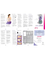
OFFEN
OFFEN
GESCHLOSSEN
U1
U2
VERBRAUCHER
VERBRAUCHER
Anschluss
Fernsteuerung
Die Schutzabdeckung der Klemmen wieder
anbringen
H
.
Elektrische Anschlüsse
Der Anschluss hängt von den von der Ther-
mostatsteuerung gesteuerten Geräten ab.
ZEICHENERKLÄRUNG
Netzstromleiter
N = Neutralleiter
L = Leiter
Relaiskontakte
C = allgemeiner
NO = normalerweise offener Kontakt
NC = normalerweise geschlossener
Kontakt
Stromverbraucher
U1 = Brenner, Umwälzpumpe, Magnet-
ventil, usw.
U2 = motorisiertes Ventil
Eingangskontakte für Fernsteuerung
1. Eingang
2. Eingang
HINWEIS. Beim Anschließen die Anleitun-
gen des zu steuernden Geräts beachten.