


CV-940 Series
Page 5 of 19
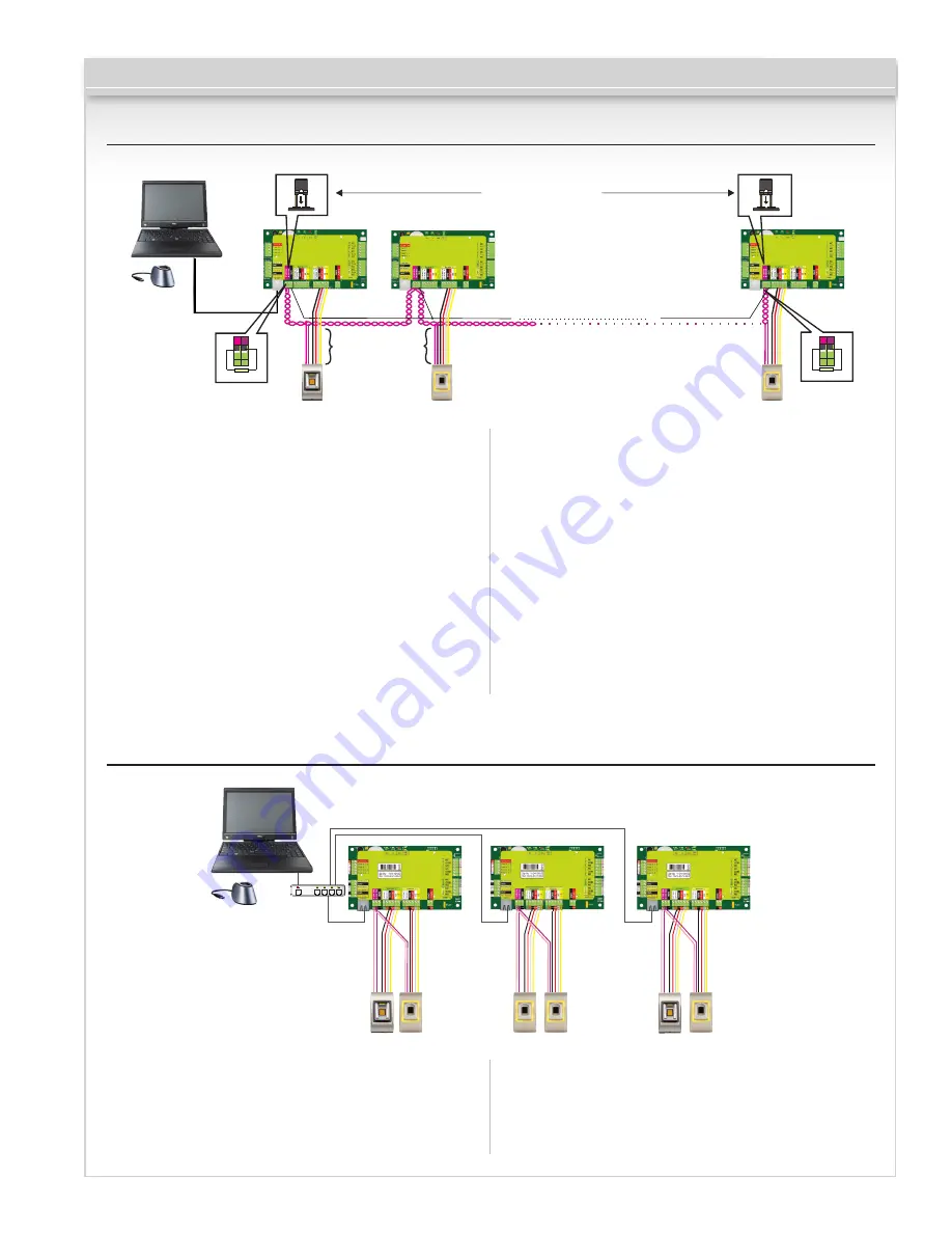
5.1 Connecting Biometric Readers In Same RS485 Line with the CV-350 Controllers
• The Biometric readers are connected through a RS485
bus. The same RS485 bus that the CV-350 controllers
are connected to.
• Maximum units in one network (CV-350 + Biometric
readers) is 32.
• If there are more than 32 units in one network, please
utilize a RS485 HUB to connect.
• The RS485 Line should be configured in the form of a
daisy chain, NOT in a form of a star. If a star must be
used in some points, keep the stubs from the RS485
backbone as short as possible. Maximum length of
the stub is dependant of the installation (total number
of devices in RS485 line (total cable length,
termination, cable type...) so recommendation is to
keep stubs shorter than 16 1/2 meters, keeping
in mind that this can cause errors in communication
with PC software
• The cable must be twisted and shielded with a
min 0.01” in (0.2 mm) 2 cross section.
• Connect the ground (0V) of each unit in the RS485
Line using a third wire in the same cable.
• The shield of the communication cable between two
devices must be connected to the EARTH from ONE
side of the RS485 Line. Use the side that has earth
connection to the building’s grounding network.
RS485
3,280 ft. (1 km) max. / 32 Units
(CV-350 + Biometric Readers)
50 ohm
50 ohm
TCP/IP
gnd
gnd
Stub
Jumper for
RS485 termination
16 ft.
(5m) max.
5.2 Connecting Biometric Readers When All The Controllers Have
TCP/IP Communication
TCP/IP
164 ft.
(50m)
max.
164 ft.
(50m)
max.
164 ft.
(50m)
max.
Switch
• When all the controllers are connected via TCP/IP, then
the RS485 network becomes local (from Reader 1 to
the Controller then to the Reader 2).
• Connect the readers directly to the RS485 terminals in
each controller.
• If the distance Reader-Controller is high 164’ (50meters)
and if the communication with the reader can not be
established, then terminate the RS485 network by
closing the jumper in the CV-350 Controller or as
described in chapter 4.


