UNDER DEVELOPMENT
Page 31
2 At the LPU end only: Fit one cable gland and one RJ45 connector by following the
procedure described in
Terminating the main drop cable
on page
23
:
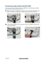
3 At the LPU end only: Connect this cable and gland to the bottom LPU by following the
procedure
Connecting a drop cable to the ODU and LPU
on page
20
.
4
At the PSU end only: Do not fit a cable gland. Strip the cable end and fit the RJ45 connector
load bar. To use the rotary blade tool, fit it around the outer cable sheath and rotate the
cutter around the cable once or twice, then remove the stripped outer section:
5
At the PSU end only: Fit the RJ45 connector housing as shown. To ensure there is effective
strain relief, locate the cable inner sheath under the connector housing tang:


