Page 18
UNDER DEVELOPMENT
Installing the copper Cat5e Ethernet interface
For all installations, install a copper Cat5e Ethernet interface from the ODU (PSU port) to the
PSU. For advanced installations, install copper Cat5e Ethernet interfaces from one or both of the
SFP and AUX ports to a linked device (see Note below).
Caution
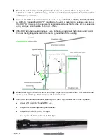
To provide effective protection against lightning induced surges, grounding cables must
be installed without drip loops and pointing down towards the ground. The drop cable
must not be laid alongside a lightning air terminal.
Caution
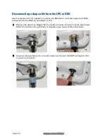
To avoid damage to the installation, do not connect or disconnect the drop cable when
power is applied to the PSU or network terminating equipment.
Caution
Do not connect the SFP or AUX drop cables to the PSU, as this may cause equipment
damage.
Note
These procedures apply when installing copper Cat5e Ethernet interfaces into the SFP or
AUX ports of the ODU, but with the following differences:
•
In SFP copper Cat5e interfaces, install a copper SFP module in the ODU (SFP port).
Connect the SFP drop cable into this module using the long cable gland from the
SFP module kit. The
PTP 650 Ethernet SFP Module Installation Guide
(supplied with
Cambium Networks SFP modules) describes how to do this.
•
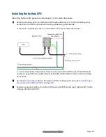
PTP 650 LPUs are not suitable for installation on SFP copper Cat5e interfaces. For
SFP drop cables, obtain suitable surge protectors from a specialist supplier.
•
At the remote end of an SFP or AUX drop cable, use an appropriate termination for
the connected device (network device, linked ODU, video camera or wireless access
point). The below instructions for connection to the PSU may have to be modified.
•
If the connected device is outdoors, not in the equipment building or cabinet, adapt
the grounding instructions as appropriate.
Note
When installing an optical Ethernet interface into the SFP port of the ODU, follow the
PTP 650 Ethernet SFP Module Installation Guide
(supplied with Cambium Networks SFP
modules).


