background image


CS3000 User’s Guide 

56 


Calsense 

Suspending or Preventing Irrigation 

No Water Days 

The No Water Days feature allows the user to suspend scheduled irrigation for a specific Station Group 

on a controller for a number of days. This is typically used due to significant rainfall, special events, or to 

prevent irrigation during scheduled construction. 

Caution:


No Water Days affects stations assigned to Manual Programs as well. If attempting to suspend 

scheduled irrigation and run a Manual Program instead, remove the start time or water days from the 

Station Group instead. 

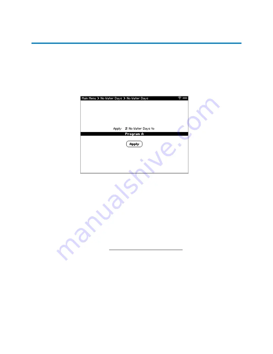
To set or remove No Water Days (Figure 45): 

1.


From Main Menu, navigate to 

No Water Days

 and select 

No Water Days

. The No Water Days 

screen displays. 

2.


Use 

+/-

 to set the number of calendar days to skip irrigation. 

3.


Use 

+/-

 to select the desired Station Group or 

All Station Groups

4.


Select 

Apply

 to set the no water days. A confirmation window displays. 

5.


Select 

OK

 to close the window. 

Once the No Water Days are set, they can be cleared the same way. Alternately, to set or remove No 

Waters Days from a single station, see Individual Station Irrigation Schedule. 

Turn Controller Off 

Turning the controller off stops all current and prevents all future scheduled irrigation, including Station 

Groups and Manual Programs, on this controller and any other controllers on the same 

FLOWSENSE


chain until it is turned back on. It does not physically power off the controller. 

Figure 45: No Water Days Screen 

Summary of Contents for CS3000

Page 1: ...CS3000 USER S GUIDE...

Page 2: ...Contact Information calsense com Phone 760 438 0525 Toll Free 800 572 8608 Technical Support Online calsense com E mail customerservice calsense com...

Page 3: ...available from the website as is No warranty or support is provided Calsense assumes no responsibility or liability for any errors or inaccuracies that might appear in this document Additionally the...

Page 4: ...WSENSE 12 Water Management 12 Flow Monitoring 12 Sharing Data Between Controllers 13 Device Compatibility 14 2 Wire Decoders 14 2 Station 2 Wire Decoder 14 POC Decoder 15 Soil Moisture Sensor Decoder...

Page 5: ...g Mainline Status 29 Viewing POC Status 29 Additional Steps for 2 Wire 30 Discovering 2 Wire Decoders 30 Assigning Stations to 2 Wire Decoders 31 Assigning POCs to 2 Wire Decoders 32 Scheduling Irriga...

Page 6: ...e Sensors to Station Groups 48 Unlinking Orphan Station Decoders 49 Unlinking Orphan POC Decoders 50 Manual Water Operations 51 Testing Stations 51 Manually Watering 52 Manual Programs 53 Manually Ope...

Page 7: ...69 Irrigation Reduction within Budget 69 Comparing Actual Usage to the Budget 71 Lights 72 Scheduling Lights 72 Turning Lights On or Off 73 Viewing Lights Status 73 Viewing Lights Summary 74 Communica...

Page 8: ...lant material head type sun exposure to groups of stations to simplify programming of stations with similar characteristics Support for managing flow on up to four mainlines and 12 points of connectio...

Page 9: ...included in the Calsense products such as our cloud based central control application Command Center Online This service is provided at no charge to the customer to ensure our customer s site is succ...

Page 10: ...nsient and lightning protection and factory labeled terminals It also features a security tight locking mechanism louvered vents with splash guards and bee wasp screens Wall mount options 1 and 2 incl...

Page 11: ...nit comes complete with transient and lightning protection factory labeled terminals GFCI outlet and keyed switch It also features a security tight locking mechanism louvered vents with splash guards...

Page 12: ...onventional station controller and one 2 Wire controller model CS3 8 2W SD The enclosure is constructed of weather and vandal resistant stainless steel The unit comes complete with transient and light...

Page 13: ...teries a power inverter a power monitor and circuit breakers Pre assembled and pre wired for convenience the CS3 SL offers up to 48 stations or as a 2 Wire controller all featuring the CS3 GR KIT comm...

Page 14: ...Flow Meter Water Management With FLOWSENSE the user can control the number of valves turned on based on the flow capacities of each mainline This minimizes the water window thus the allowable mainline...

Page 15: ...Yes or No If Yes i Navigate to FLOWSENSE address and use to change internal communication address of controller The controller with the internet connected device should be addressed A The other contro...

Page 16: ...k Diagnostic information is gathered automatically from each decoder on a continual real time basis and recorded and transmitted back to the controller as well as the Command Center Online cloud appli...

Page 17: ...rowth and to manage the amount of irrigation water applied The model CS 2W MOIST is used in conjunction with the 2 Wire option model CS3 2WIRE OPT offered only with the Calsense model CS3000 irrigatio...

Page 18: ...rates are within the operating range of the selected Flow Meter size in the table below For systems with a large mainline consider using multiple Flow Meters configured as a bypass manifold to read bo...

Page 19: ...troller with the weather option model CS3 W KIT to keep a record of accumulated rainfall and adjust irrigation accordingly Wind Gage Wind speed can be monitored by a Calsense CS3000 controller using a...

Page 20: ...pabilities of the system System reports include complete records of the details for every irrigation cycle water usage versus water budget amounts the gallons and percentages of water savings and what...

Page 21: ...ual Watering and Test Cycles If multiple types of irrigation are running you may need to press the button more than to stop it all since it only stops one type at a time ENGLISH ESPANOL toggles the te...

Page 22: ...de additional information No stations are watering Takes the user to the Irrigation Details screen Irrigation is running Takes the user to the Irrigation Details screen There will be no scheduled irri...

Page 23: ...s taken place Alerts are automatically uploaded to Command Center Online within 15 minutes of being generated To view Alerts 1 From Main Menu navigate to Diagnostics and select Alerts The Alerts repor...

Page 24: ...t from the list of stations to irrigate until the next time it is scheduled to run or is turned on manually 3 When finished press BACK to return to the Main Menu Viewing Station Group Finish Times The...

Page 25: ...art Time Note If the system has more than one mainline press NEXT or PREV to view Station Groups assigned to the additional mainlines 3 To edit the Start Time navigate to and select the desired statio...

Page 26: ...in Menu navigate to Setup and select Date Time The Date Time screen displays 2 Navigate to Time Zone and use to adjust the time zone if necessary 3 Navigate to the date and time and use to change valu...

Page 27: ...ting Note Depending on when the controller was manufactured you may or may not have the backlight feature 3 When finished press BACK to save changes and return to the main menu Disabling Stations The...

Page 28: ...tent If too many valves are on at a time the water pressure loss will result in poor coverage To set on at a time Figure 15 1 From Main Menu navigate to Mainlines and select On at a Time 2 Navigate to...

Page 29: ...and select the corresponding city in the list provided The pre populated Historical monthly ET numbers for that location display iv Navigate to Amount of Historical ET to limit daily ET and use to adj...

Page 30: ...nd select the desired Mainline or Add New Mainline to add additional mainlines The CS3000 supports up to four independent mainlines 3 Navigate to Mainline name and press SELECT to edit the name with p...

Page 31: ...e to Diagnostics and select Live Screens Live Screens menu displays 2 Navigate to and select Mainline Status Mainline Status menu displays 3 When finished press BACK to return to Main Menu Viewing POC...

Page 32: ...Wire path after they have been installed This simplifies installation by allowing all decoders to be installed in the field without any pre programming To discover all 2 Wire decoders attached to the...

Page 33: ...red Decoders The Station Assignment screen displays 3 Navigate to desired Decoder by serial number S N and press SELECT 4 Navigate to Station under Output A black wires and use to assign a station num...

Page 34: ...re The 2 Wire dialog displays 2 Navigate to and select POC Assignment POC Assignment menu displays 3 Navigate to the desired POC Decoder by Serial Number and press SELECT 4 Navigate to Is this POC Dec...

Page 35: ...ow closing valves requiring a delay before closing but retain all of the other settings To add a new Station Group 1 Highlight and select Add New group The Create New Group dialog displays 2 Select an...

Page 36: ...or sprinkler type selections to choose from for each zone The options are Spray Spray Stream Spray High Efficiency Rotor Full Circle Rotor Part Circle Rotor Mixed Rotor Stream Impact Full Circle Impac...

Page 37: ...he unique circumstances at each site To adjust this setting highlight the field and press to increase or decrease the value Setting up Crop Coefficients Crop Coefficients take properties of plants and...

Page 38: ...Prioritizing Station Groups The Priorities feature allows station groups to irrigate before other groups depending on the priority level High Medium and Low Priority levels establish the order of whi...

Page 39: ...To edit the Percent Adjust screen Figure 26 1 From Main Menu navigate to Scheduled Irrigation and select Percent Adjust The Percent Adjust screen displays 2 Navigate to desired station group 3 Naviga...

Page 40: ...feature only activates pumps wired to the CS3000 controller Note Pump and non pump stations will not irrigate at the same time To edit the Pump Use screen Figure 27 1 From Main Menu navigate to POCs...

Page 41: ...Irrigation and select Stations The Stations menu displays Adjusting Stations Settings Adjusting Run Time Station Adjust is used to increase or decrease the run time of an individual station using dai...

Page 42: ...rrigate other stations that are eligible to run This Soak Between Cycles is automatically calculated based on the Station Group s soil type precipitation rate and distribution uniformity This default...

Page 43: ...lity to test a station or acquire an expected flow rate for a station When a station is being tested it will ignore On At A Time and flow checking rules To learn how to test a station see Testing Stat...

Page 44: ...f minutes the station ran for and how many gallons were consumed Types of irrigation included programmed irrigation manual test walk thru and mobile To view the Station Summary Report Figure 30 1 From...

Page 45: ...to calculate each station s irrigation time based on the total ET for all days since the last irrigation Additionally by using the site s physical conditions such as plant material head type and expos...

Page 46: ...rcentage indicates how full the gage is This value reduces automatically as ET is measured After refilling and priming the gage this should be set back to 100 If the ET Gage was primed or repaired it...

Page 47: ...10 minutes or until the wind dies down The Resume setting indicates at what speed in mph the controller should resume irrigation after pausing due to wind Setting up a Third Party Rain Switch The Rai...

Page 48: ...ors and select Freeze Switch The Freeze Switch screen displays 2 Specify whether the controller uses a freeze switch to prevent irrigation When set to Yes a list displays showing the controller or all...

Page 49: ...value The specify historical values see Reference ET Values For rain values Rain indicates the controller received enough rain to cross the minimum threshold to stop irrigation Minimum indicates rain...

Page 50: ...ed moisture sensor by serial number 4 Navigate to and select Sensor Name to edit the name with the pop up keyboard Select OK when done 5 Navigate to and select Assign Sensor to Station Groups The Stat...

Page 51: ...from the system For example if a decoder has been damaged it may need to be replaced with a new decoder After removing a decoder and performing a 2 Wire discovery the station s assigned to that decod...

Page 52: ...dialog This allows these POCs to be unlinked from the missing decoder thereby making them available to assign to a new decoder To Unlink Orphan 2 Wire POCs Figure 39 1 From Main Menu navigate to Setu...

Page 53: ...ations The Test Stations screen displays 2 Use to select desired station If the controller is part of a FLOWSENSE chain make sure you select the correct controller as well 3 To adjust the amount of ti...

Page 54: ...er irrigation will be paused until the Manual Watering completes To manually water a station Figure 41 1 From Main Menu navigate to Manual Test and select Manual Watering The Manual Watering screen di...

Page 55: ...Program or select Add new program to create a new one from scratch 3 For Program name press SELECT and enter a name to uniquely identify the program using the on screen keyboard 4 For Schedule use to...

Page 56: ...close a master valve now 1 From Main Menu navigate to Manual Test and select Master Valve Override The Master Valve Override screen displays 2 If there is more than one Mainline select which mainline...

Page 57: ...Thru screen displays 2 Navigate to and select the desired Walk Thru program or select Add Walk Thru 3 For Walk Thru name press SELECT and enter a name to uniquely identify the program using the on sc...

Page 58: ...u navigate to No Water Days and select No Water Days The No Water Days screen displays 2 Use to set the number of calendar days to skip irrigation 3 Use to select the desired Station Group or All Stat...

Page 59: ...affected If all irrigation needs to be stopped Calsense recommends physically powering off the controller To turn off the controller Figure 46 1 From Main Menu navigate to No Water Days and select Tur...

Page 60: ...ownstream of the Flow Meter tee This applies to distance from any valve pipe fitting water meter or backflow device The length of 14 gauge AWG wire connecting the Flow Meter to the CS3000 Irrigation C...

Page 61: ...minal based POCs not 2 Wire Configuring a Bypass Manifold A bypass manifold allows low flow readings on a large mainline It does so by utilizing one or two smaller flow meters attached to a large main...

Page 62: ...use to select set which decoder operates this level b For Master Valve use to select Master Valve type Note that only the smallest size may have a normally open Master Valve All other levels must be...

Page 63: ...w for the subsequent irrigation Delay Between Valves The Delay Between Valve Times feature provides the ability to stop the next valve from turning on after a particular valve closes This is commonly...

Page 64: ...lues and should be set above the combined flow rate of any stations that irrigate at the same time The Master Valve Override value monitors for breaks during a scheduled or manual Master Valve Overrid...

Page 65: ...eature Several thresholds display 4 For each threshold a Use to set the flow boundaries for that threshold b Use to adjust the high and low flow rate rates in the Allowable Range Column 5 Continue to...

Page 66: ...d when the high or low flow occurs but not additional action is taken This is commonly used when low flows are detected Alert Shutoff An alert is generated and the valve is shutoff This is commonly us...

Page 67: ...consumed for each type of irrigation including scheduled manual test and so on To access the Mainline Summary report Figure 55 1 From Main Menu navigate to Reports and select Mainline Summary Mainlin...

Page 68: ...etup screen displays 2 Navigate to the desired Mainline 3 For Compare use to a budget and select Yes to enable use of a budget Several fields display to configure the budget 4 For POC budget amount se...

Page 69: ...Budget c To enter the budget amounts now select Enter POC Budget Amounts and see Defining a Budget for each Billing Period for steps to do so If selecting Calculated using Annual Figure 57 a For Budge...

Page 70: ...alculate Square Footage This calculation uses the station s expected flow rate and precipitation to estimate the area the station covers Note Selecting this will not overwrite any square footages that...

Page 71: ...a select the option at the bottom of the screen Configuring Usage that Impacts the Budget Defining Flow Types Included in Budget provides the ability to exclude specific usage from being included whil...

Page 72: ...important to consider plant needs while adjusting these settings For example there may be a cost associated with going overbudget However that cost is likely much less than having to replace trees th...

Page 73: ...d to the budget for the current period To access the Use vs Budget screen Figure 62 1 From Main Menu navigate to Budgets and select Use vs Budget The Use vs Budget report displays 2 Navigate to the de...

Page 74: ...ller each with a two week rolling schedule and two 2 start and stop times per day After completion of the two week schedule the schedule rolls over and begins again continuously until the user turns t...

Page 75: ...o select the Light Schedule to turn on or off If the Lights are on i For Turn OFF at select what time to turn the lights off ii Select Turn OFF If the Lights are off i For Turn OFF at select what time...

Page 76: ...play Viewing Lights Summary The View Lights Summary provides a daily record of lights activity To view details of when lights turn on and off Figure 66 1 From Main Menu navigate to Reports and select...

Page 77: ...vice This is commonly used with small FLOWSENSE chains COMM 1YR 35 provides up to 35 controllers with 12 consecutive months or one year of data communication service This is commonly used with larger...

Page 78: ...ns screen displays 3 For Test radio communication with select either CS3000 or ET2000e If you select CS3000 use to enter the serial number of a CS3000 to test communication with If you select ET2000e...

Page 79: ...to activate software options such as FLOWSENSE model CS3 FL and Hub model CS3 HUB OPT using an activation code 1 From Main Menu navigate to Setup and select Communication Options The Communication Op...

Page 80: ...and adjust according Electrical Short Unknown Output An electrical short was detected from an unknown output Power surge Wires are crossed Adjust wire placement Wire splices are not watertight Locate...

Page 81: ...ne break was detected while irrigating Broken head Locate the break and then fix or replace part To many valves are in use at one time Adjust number of valves in use Broken laterals fittings Locate an...

Page 82: ...orted together Replace wires and adjust positioning Solenoid Short Station num An electrical short was detected on indicated station Solenoid is shorted out Replace solenoid Bad splices Repair splices...

Page 83: ...le below to determine the soil type For a more detailed and accurate soil description collect a sample from the site to send to the nearest soil lab Controller Behavior The expected controller behavio...

Page 84: ...ation rates between 0 25 1 5 inches hour 360 degrees Radius of 15 100 feet Rotor Part Circle Single stream of water rotating back and forth at adjustable angles less than 360 degrees Operating pressur...

Page 85: ...60 psi and precipitation rates 0 20 2 0 gallons minute Radius up to 1 5 feet per emitter Drip Emitter Applies water directly to plants root zone at a single point or multiple points along a pipe Oper...

Reviews: