California Instruments 1001P Series Training Manual Download Page 27

PGUI / PGUI32 Training Manual

1.1

27

6. 
Transient Programming

Transients are a powerful feature of California Instruments AC Sources. To get the most out of the

AC Source and PGUI program, it helps to understand how the PGUI implements transient
programming.

The California Instruments’ P Series and RP Series do not have transient generation capabilities

built into the AC Source controller. Instead, the PGUI is used to program the output of the AC Source
under the control of a user specified transient list. The PGUI provides an easy data entry format for
programming this transient list. Since transient execution is performed by the PC, the interface option
(either IEEE-488 or RS232C) is required. This means that you cannot run transients from the front
panel of the P or RP.

A transient list ends when you run out of steps (100 max.) or when the PGUI encounters an empty

transient type.

The following exercises will make the process of creating and running transients more clear.

6.1 Voltage Transients

Voltage transients only affect the output voltage. Typical voltage transients are drops, steps, surges,

sags and sweeps. Each transient step has a start and stop value for the voltage and a duration time. We
will set up a few different voltage transients as an exercise:

Exercise:

1. Select the Transient menu which will bring up the Transient window.

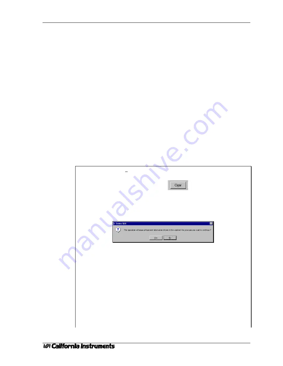
2. Clear the present contents by clicking on the Clear All key located in the

bottom right corner of the Window. 
You will be asked to confirm since this action wipes out the entire grid
contents. Click on Yes to acknowledge the fact that you do indeed want to start
from an empty grid. Note that the PGUI always recalls the last Transient setup
present when the Close button was clicked. This always allows you to go back
to your last transient program, even if you did not save it explicitly.

3. Go to the first row of the grid (step No 1). Transient programs always start
execution from step No. 1.

4. Click on the drop down box and select the ‘V Step’ transient type.

5. Tab over to the ‘Time (s)’ field and enter 0.02. This corresponds to 20
millisecond which is the minimum time interval for most transient events except
the Voltage Drop (10 ms) and the combined VF transients (40 ms).

6. Tab over to the right or click on the Voltage field. Notice that only those
fields that have to be entered are white. All unused fields for the V Step
function are grayed out. You can enter values in these fields but they will be
ignored and any time you move to a new register, grayed out values will be
erased.

7. Enter ‘120.0’ for 120 Vrms. Note that if you are in the Low Voltage range,
you should not enter values above the range limit of 270 Vrms. If you do, you

Summary of Contents for 1001P Series

Page 1: ...PGUI or PGUI32 TRAINING MANUAL P Series RP Series Graphical User Interface Software 1251RP Programmable AC Source Revision 1 1 Date June 24 1998...

Page 2: ...PGUI PGUI32 Training Manual 2 1 1...

Page 3: ...17 3 4 Command Menu 18 3 5 Toolbar 18 3 6 Next 18 4 System Menu 19 4 1 Interface 19 4 2 Configuration Settings 21 4 3 Power On Settings 22 5 Measurements 23 5 1 Enable and Disable Measurements 23 5 2...

Page 4: ...PGUI PGUI32 Training Manual 4 1 1...

Page 5: ...a single AC source and will ignore all other types of instruments connected to the same bus It is possible however for other Windows programs to run at the same time as the PGUI and control other inst...

Page 6: ...Users of Windows NT have to use the 32 bit PGUI32 The 16 bit program will not run under NT PC Based IEEE 488 Interface Controller RP Series AC sources can be controlled remotely using either the IEEE...

Page 7: ...P Series RP Series 1001P 801RP 1251P 1251RP 2001RP PGUI32 only If you do not have one of these units connected to your PC or have a suitable interface in your PC yet you can still proceed with this t...

Page 8: ...PGUI PGUI32 Training Manual 8 1 1...

Page 9: ...ion procedure is very similar except you use the Program Manager s File Run menu to start the SETUP program located on the installation disk 2 1 Windows 95 Installation procedure To install the AC sou...

Page 10: ...e Programs icon to launch the Windows 95 Add Remove Programs property dialog 4 Click on the Install button located in the top right corner of this dialog box 5 Insert the first installation disk in dr...

Page 11: ...rectory for the AC source control software which is PGUI on the current drive At this time you can accept the default directory by clicking on the OK button or enter a different directory If the direc...

Page 12: ...it will be created 11 The setup program will create a program group The default group name used will be PGUI You may also elect to store the AC source control program icon in a different group You ma...

Page 13: ...disk In Windows 95 the installation program will create a Start menu program group called PGUI and a program shortcut also called PGUI We recommend you keep the distribution disk in a safe place in c...

Page 14: ...PGUI PGUI32 Training Manual 14 1 1...

Page 15: ...ry to connect to the AC Source if it was connected at the time the program was closed If not or if the AC source cannot be found at the same IEEE address or serial port the PGUI will launch in simulat...

Page 16: ...function of the speed at which you drag the slider handle 3 2 By clicking on the arrows located at the left or right end of the control This changes the frequency at 0 1 Hz increments 3 3 By clicking...

Page 17: ...e can be used to release the unit for front panel access There are situations in which it may be necessary to use the front panel 3 3 Status Bar PGUI status bar Program and interface status PGUI32 sta...

Page 18: ...th a single mouse click As you get more familiar with operating the PGUI you may rely on the Toolbar more and more as it gets you to the right screen faster Each Toolbar button has a yellow tooltip th...

Page 19: ...Exercise 1 Pull down the System menu and select the Interface sub menu or click on the IEEE connector symbol in the Toolbar This will bring up the Interface window 2 If you are operating in Simulatio...

Page 20: ...unicate with the AC source and an error message will appear Note that the P Series does not offer an IEEE 488 interface so you have to use RS232C The RP Series offers both interfaces 6 If you have a u...

Page 21: ...AC source These settings are determined by the AC Source configuration and cannot be changed by the user Exercise 1 Select the Configuration sub menu from the Source menu 2 Verify that the limits and...

Page 22: ...front panel setup register 2 as the power on default and click on Close to close the Power on Setting window 3 Next we need to make sure the setup we want the unit to power up in is indeed stored in s...

Page 23: ...ge measurement accuracy Sudden changes in output voltage will not appear immediately due to this averaging technique The PGUI normally continuously polls the measurement data from the AC Source You ca...

Page 24: ...xercise we will use training csv 3 Select the Overwrite mode if it is not already selected This will cause a new file to be started each time you start a measurement cycle 4 Select the ASCII string Ti...

Page 25: ...l or Notepad if Excel is not available to you The following table shows a fraction of the data file 1997 09 17 12 42 23 PGUI Training Manual Date Time F V I 9 17 97 12 42 25 50 271 4 5 9 17 97 12 42 2...

Page 26: ...PGUI PGUI32 Training Manual 26 1 1...

Page 27: ...e transients as an exercise Exercise 1 Select the Transient menu which will bring up the Transient window 2 Clear the present contents by clicking on the Clear All key located in the bottom right corn...

Page 28: ...ent system accordingly 11 Enter 20 0 V for the Voltage value This will cause the voltage to sweep down from the 120 V entered in step 1 to 20 volt 12 Move to the next step No 3 and select V Srg Sag as...

Page 29: ...nds 3 Set Frequency field to 500 00 Hz This will cause the frequency to sweep up from its present steady state value to 500 Hz 4 Move to the next step and select F Sweep again as the Transient Type Ta...

Page 30: ...or a 40 msec time Set the Voltage field to 0 0 V Set the Frequency field to 50 00 4 Move to the second row No 2 and select the VF Sweep transient type 5 Set the Time s field to 3 000 for a 3 second sw...

Page 31: ...e the transient list Time delays can be entered in one of two ways Time in Seconds default mode Time is entered in actual seconds Time in Cycles Time is entered in cycles The length of each cycle is a...

Page 32: ...ing the last transient program we have created click on the Save button 2 This brings up the File Save dialog box shown here 3 The default directory is the PGUI program directory You can change to any...

Page 33: ...mpted for a file name If you saved the setup before or you recalled a setup from disk the same setup filename will be used for any subsequent save operations unless you use the Save As sub menu option...

Page 34: ...settings are different from the one you just saved 2 Pull down the File menu and select the Open sub menu This will show you a list of all setup files in the working directory 3 Select the training s...

Page 35: ...ed with the program All windows have a Help button which gets you directly to the relevant help topic You can also use the Help menu to see the help table of contents or do a search on a specific topi...

Reviews: