MANUAL
1
2
3
4
MUTE
▲
MENU
5
MODE
ENT
11
6
12
USB
7
13
SD
8
14
Basic Operations
9
B
A
A
M
N
S
D
VOL-
SEL
VOL+
15
10
16
Installing the lithium coin battery (CR2025)
1
2
3
17
●
Aim the remote control directly at the remote sensor on the unit
4
5
6
18
●
DO NOT expose the remote sensor to strong light
7
8
9
0
19
(direct sunlight or artificial light)
WARNING: To prevent accidents and damage
●
DO NOT install any battery other than CR2025 or its equivalent
●
Store the battery in a safe palce where children cannot reach
●
DO NOT charge, decompose,heat up the battery or dispose it in a fire.
●
DO NOT poke or pierce the battery with tweezers or similar tools.
●
Wrap the battery with tape for insulation when throwing it away for
keeping it for future use.
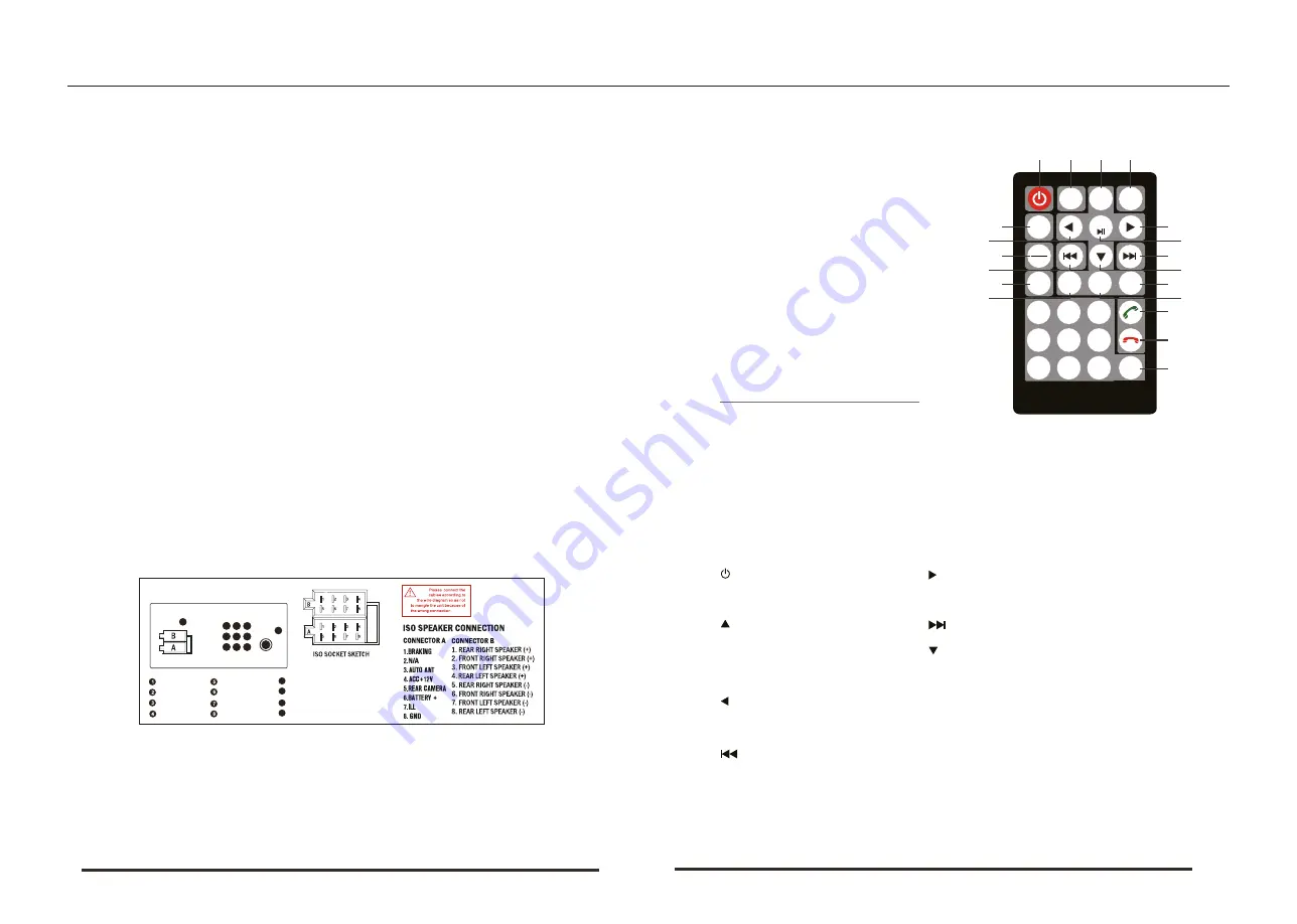
1. Power switch
11. Left
2. Mute
12. Confirm / Play / Pause
3. Up
13. Next song
4. Menu
14.
Under the
5. Mode switch
15. Volume -
6. Right
16. Choice
7. USB / SD
17. Answer the phone
8. Last song
18. Hang up
9. Band / Automatic
19. Digital key
10.
2
1
The unit is designed for 12V DC negative ground operation system only.
Before installing the unit, make sure your vehicle is connected to DC12V
negative ground electrical system.
The negative battery terminal must be disconnected before making
connections, which can decrease the chance of damaging the unit due to
short circuit.
Be sure to connect the color coded leades correctly according to the
diagram. Incorrect connection may cause the unit malfunction or damage the
vehicle’s electrical system.
Be sure to connect the speaker (-) leads to the speaker (-) terminal. Do not
connect the left and right channel speaker cables to each other or to the vehi-
cle body.
Do not block vent or radiator panel. Blocking them will cause heat build up
inside and may result in fire.
After the completion of the installation and begin to play the unit (including
replacing the battery), please press the RESET button on the front panel with
pointed objects (such as ball-point pen) to set the unit to initial status.
1. Notes On Installation
3. Remote Control Description
2. Wiring Diagram
1
2
3
4
5
6
7
8
9
10
11
12
ISO SOCKET SKETCH
9
10
11
12
SUB-OUT
REAR-R-OUT
REAR-L-OUT
VIDEO-OUT
AUX-AUDIO-R-IN
AUX-AUDIO-L-IN
REAR-CAM-IN
FRONT-CAM-IN
AUX-VIDEO-IN
RADIO-Antenna
GPS (OPTIONAL)
DAB(OPTIONAL)


