8
Electrical installation
1
2
3
4
5
6
7
8
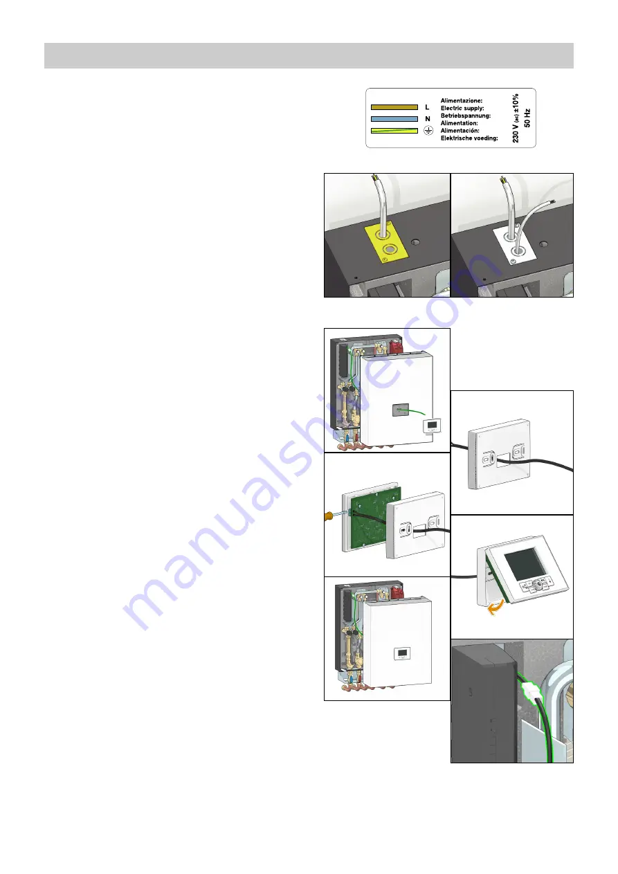
Connection to the electric supply
The appliance is supplied with an electric supply cable which is not
fitted with a plug.
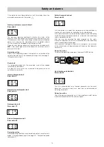
The appliance should be electrically connected to a 230 V (ac) single-
phase + earth mains supply using the three-wire cable marked with
the label as specified aside, observing the LIVE (L) - NEUTRAL (N)
polarities and the earth connection. This line must be connected to a
circuit breaker device.
To extend the cable if necessary, use a flexible cable suitable for
kitchen and heating appliances and for home, kitchen and office
installations, also in humid environments subject to medium levels of
mechanical stress (e.g. H05V2V2-F: Uo/U 300/500 V). Cable
minimum cross-section 3 x 0,75 mm
2
.
Make sure that the electrical system can withstand the maximum
power consumption of the appliance, with particular emphasis on the
cross-section of the wires.
If you have any doubts, contact a qualified technician to request a
thorough check of the electrical system.
Electrical safety of the appliance is only achieved when it is correctly
connected to an effective earthing system, constructed as specified in
current safety regulations. This is a compulsory safety requirement.
Observe the applicable regulations in force in the country of
installation.
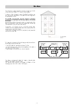
Use the cable pathway provided, as shown in figure 1.
Optional electric connections
The controller has a door on the front providing access to terminal
boards for optional wiring (see chapter “circuit board details”). The
connections in question are all low voltage or potential-free. Any wiring
must be directed toward the exterior of the HIU, using the pathways
provided in the insulation and on the frame. All the low voltage lines
must be routed through a single dedicated cable raceway, using the
pathway that is not used for the electric supply cable (see figure 2), so
that they are separate from the 230 V electric cables.
Any other high voltage connection, e.g. the one from the auxilliary
microswitch (see pages 13 and 16) must pass through the same cable
pathway used for the main electric supply.
Remote user interface connection
The HIU user interface has the dual function of control device and
room thermostat. The remote user interface can be installed on board
the HIU or in the room in a position where the temperature
measurements will be of significance for control of the heating function
(in a heated room in a position where the temperature read by the
thermostat is not affected by any nearby heat sources).
Installation on board the HIU
If the remote user interface is fitted in the dedicated location on the
cover of the HIU, the thermostat function must be disabled (in this
case an external thermostat must be used, as described in the next
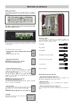
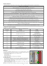
section). The adjacent figures show how to install the remote control
unit:
- Feed the cable from the regulator through the hole in the cover (3);
- Feed the cable from the regulator through the rear of the interface
(4);
- Connect the two wires to the terminals on the electronic circuit
board (the cable is not polarised) (5);
- Close the interface and position it in its housing on the cover (6), (7);
- If necessary, secure the interface from inside the cover by means of
the supplied pair of self tapping screws, spacers, and washers;
- Plug in the connector (8).
The thermostat function is enabled by default (refer to the
remote control user manual for disabling it).


