SERVICE MANUAL
CALIBRATION
3-29
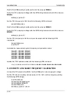
Reset the TW back to AC coupling mode, output off.
SOUR
{1,2,3}
:VOLT:OFFSET 0.0
OUTP OFF
OUTP:COUP AC
Calculate the gain from the collected data:
GAIN
= (
RDGN2
–
RDNG1
) / (
MEAS2
–
MEAS1
)
Update the TW’s gain setting using the GPIB strings below:
CAL
{1,2,3}
:MEAS:LOC:LOR:CURR:GAIN
GAIN
CAL
{1,2,3}
:MEAS:REM:LOR:CURR:GAIN
GAIN
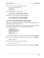
3.20 LOCAL LOW RANGE WATTS CALIBRATION
Connect the 12 ohm resistor to the output of the TW through the power analyzer. Set
up the power analyzer to measure watts.
Set up the TW to AC coupling, low range, local sense, 13 ampere current limit, output
relay closed and 54 volts with the following GPIB programming strings:
OUTP:COUP AC
SOUR:VOLT:RANGE LOW
SOUR:SENSE LOCAL
SOUR
{1,2,3}
:CURR 13.00
OUTPUT ON
SOUR
{1,2,3}
:VOLT 54
Wait until the power analyzer has stabilized and record the watts reading as
RDNG1
.
Query the TW’s watts using the GPIB string below, and record this value as
MEAS1
.
MEAS
{1,2,3}
:POW?
Program the TW to 134 volts AC using the string below:
SOUR
{1,2,3}
:VOLT 134
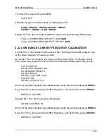
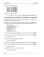
Wait until the power analyzer has stabilized and record the watts reading as
RDNG2
.
Summary of Contents for TrueWave TW5250
Page 2: ......
Page 4: ...ii This page intentionally left blank...
Page 10: ...TABLE OF CONTENTS TW SERIES viii This page intentionally left blank...
Page 36: ...MAINTENANCE AND TROUBLESHOOTING TW SERIES 2 16 This page intentionally left blank...
Page 80: ...CALIBRATION TW SERIES 3 44 This page intentionally left blank...


