SERVICE MANUAL
CALIBRATION
3-25
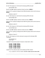
Set the TW frequency to 60 Hz and open the output via the GPIB:
SOUR:FREQ 60.0
OUTP OFF
Calculate the phase offset calibration data:
VALUE1
= -1.0 *
RDGN1
VALUE2
= -1.0 *
RDGN2
VALUE3
= -1.0 *
RDGN3
VALUE4
= -1.0 *
RDGN4
VALUE5
= -1.0 *
RDGN5
Update the calibration data via the GPIB:
CAL:UNIQ:OPHAB
VALUE1 VALUE2 VALUE3 VALUE4 VALUE5
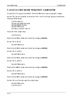
Calculate the phase angle readback calibration data:
VALUE1
= -1.0 * (
RDGN1
+
MEAS1
)
VALUE2
= -1.0 * (
RDGN2
+
MEAS2
)
VALUE3
= -1.0 * (
RDGN3
+
MEAS3
)
VALUE4
= -1.0 * (
RDGN4
+
MEAS4
)
VALUE5
= -1.0 * (
RDGN5
+
MEAS5
)
Update the calibration data via the GPIB:
CAL:UNIQ:MOPHAB
VALUE1 VALUE2 VALUE3 VALUE4 VALUE5
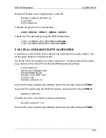
3.17 PHASE A TO PHASE C CALIBRATION
Note: this calibration step only applies to TW5250 systems.
Connect the counter timer channel 1 to the TW’s A phase through a 10:1 resistor
divider. Connect the counter timer channel 2 to the TW’s C phase through a 10:1
resistor divider. Set the counter time up to measure phase angle.
Set the TW up for 0 degrees phase A to phase C, low range, local sense, 40 Hz, 120V
and close the output by sending the following GPIB commands:
SOUR3:PHAS 0
SOUR:VOLT:RANGE LOW
SOUR:SENSE LOCAL
SOUR:FREQ 40.0
SOUR:VOLT 120.00
OUTPUT ON
Summary of Contents for TrueWave TW5250
Page 2: ......
Page 4: ...ii This page intentionally left blank...
Page 10: ...TABLE OF CONTENTS TW SERIES viii This page intentionally left blank...
Page 36: ...MAINTENANCE AND TROUBLESHOOTING TW SERIES 2 16 This page intentionally left blank...
Page 80: ...CALIBRATION TW SERIES 3 44 This page intentionally left blank...


