caenrfid Lepton9 R9100C Technical Information Manual Download Page 26


EVALUATION BOARD 

- Lepton

9

 - Technical Information Manual 

26 

Lepton

9

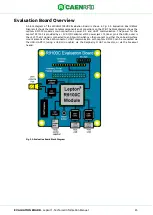
 R9100C Evaluation Board Key Components 

The  WRHML37XEVBX  Evaluation  Board  is  designed  to  allow  easy  development  of  Lepton

9

  R9100C 

applications  using  a  PC  or  other  hosts  capable  of  generating  easy2read

©

  traffic  over  UART.  It  includes 

several integrated circuit components and connectors to allow connection to USB or UART hosts, or other 
development  kits  or  customer  hardware.  These  components  are  shown  in 

Fig.

  5.3:  WRHML37XEVBX 

Evaluation Board Key Components. Components on the backside are shown with dotted lines. This section 
describes these components and connectors in detail.  


Fig. 5.3: WRHML37XEVBX Evaluation Board Key Components 


Integrated Circuit Component Descriptions 

ZZ1 is the Lepton

9

 R9100C RAIN RFID reader module. It is a completely integrated Gen2 UHF RFID reader, 

requiring  only  power,  RF,  and  UART  connections  to  read  and  write  tags.  It  is  in  a  29  by  32  mm  surface 
mountable package. 

U1 is the RF switch IC that is used to switch between the two antenna options: the onboard surface mount 
(SMT) antenna ANT1, and the SMA antenna port J2.  

ANT1  is  a  surface  mounted  far  field  fractal  antenna  for  RAIN  (UHF)  RFID  (Ignion  NN01-105).  It  uses  the 
ground plane of the evaluation board to form a read zone near the board. 

The  RF  switch  IC  is  controlled  by  a  single  input  which  is  connected  to  the  center  pin  of  the  antenna 
selection jumper J1. Removing the jumper causes the switch to connect the Lepton

9

 R9100C

’s RF port t

the SMT antenna A1. Installing the jumper in the leftmost position selects the SMA connector J1. Installing 
the jumper in the rightmost position allows the Lepton

9

 R9100C to select the antenna using GPIO1. In the 

default low state, the SMA connector J1 will be selected. In the high state, the SMT antenna ANT1 will be 
selected. The antenna can be controlled dynamically, please refer to the easy2read

©

 SDK documentation. 

The RF switch IC is a Peregrine PE42422. 

U3 and U4 are the USB-UART ICs. They allow an USB host to communicate with the Lepton

9

 R9100C module 

via 3.3 volt UART. U3 connects to the host serial interface (UART1) via the micro USB connector J4. 

U4 connects to the debug serial interface (UART2) via the micro USB connector J6. Both will be presented 
on a host as connection options. On a windows PC, they will be shown COM ports. On a linux PC, they will 
appear as /dev/ttyUSB<X>. The USB-UART IC is the Microchip MCP2200-I/MQ.  

U5 is the 3.3 volt linear regulator IC for the USB-UART ICs. The USB-UART ICs require an external voltage 
source to specify the logic level of the UART interface. This IC supplies that voltage reference and supply. 
The voltage regulator IC is a Texas Instruments TPS73533DRVR. 

U2 is the IO LED buffer IC. This buffer allows high current drive for the on-board GPIO LEDs DL2-DL7, which 
indicate the GPIO and Health and Status pin states. Without the buffer, the LEDs would load the IOs, and 
reduce the potential current supply available to custom hardware attached to the IOs. The buffer IC is a TI 
74HC4050. 

Summary of Contents for Lepton9 R9100C

Page 1: ...TECHNICAL INFORMATION MANUAL Revision 0 22 12 2022 R9100C Lepton9 30dBm 1 Port RAIN RFID Reader Module...

Page 2: ...er no responsibility is assumed for inaccuracies CAEN RFID reserves the right to modify its products specifications without giving any notice for up to date information please visit www caenrfid com P...

Page 3: ...Disposal of the product Do not dispose the product in municipal or household waste Please check your local regulations for disposal recycle of electronic products...

Page 4: ...s 17 EPC Class 1 Generation 2 Operation 18 Supported RF modes 18 4 Layout and Components 19 Introduction 19 PCB Layout for RF 19 50 Ohm Characteristic Impedance 19 Package and Assembly Information 20...

Page 5: ...L37XEVBX Evaluation Board for R9100C 24 Fig 5 2 Evaluation Board Block Diagram 25 Fig 5 3 WRHML37XEVBX Evaluation Board Key Components 26 Fig 5 4 SW2 and SW3 configuration 27 Fig 5 5 Evaluation Board...

Page 6: ...j E910 IC that permits to achieve fast reading speed and to be used in dense reader and dense tag environments for top class rated performances The compactness of the device and the surface mount tech...

Page 7: ...Mod WRHML37XDKEU WRHML37XDKUS is available The kit includes n 1 WRHML37XEVBX Lepton9 R9100C Evaluation Board n 1 Circular Polarized Quadrifilar Antenna SMA ETSI or FCC n 1 Set of Labels n 1 RT0012 Dua...

Page 8: ...D Reader Module Evaluation Board WRHML37XEVBX Evaluation Board for R1271C R3100C R7100C and R9100C Development Kit WRHML37XDKEU R1271C R3100C R7100C and R9100C ETSI Dev Kit with antenna interface pws...

Page 9: ...to FCC part 15 247 Standard Compliance EPC C1G2 ISO18000 63 I O Interface 4 I O lines 3 3V level Iout 8mA max Connectivity UART Serial Port Baudrate from 9 6 to 921 6 kbps default 921 6 kbps Databits...

Page 10: ...enna return loss Impinj RS500 and RS1000 pin to pin compatibility Inventory FastID Tag Population Estimate Select Session Target Access Read Write Lock Kill BlockPermalock and QT Shielded to prevent u...

Page 11: ...ng paragraphs Fig 3 1 Lepton9 R9100C Example of Block Diagram Required connections VDC_IN and GND are required to power the Lepton9 R9100C RF is required to connect to the UHF RFID antenna UART1 Tx an...

Page 12: ...internally bypassed and regulated and no external bypass or bulk storage capacitance is required as long as the input voltage is stable If Lepton9 R9100C activity is not required at all times and powe...

Page 13: ...uld not be applied to the NRST pin This can cause permanent damage to the device GPIO Pins The Lepton9 R9100C s GPIOs can be controlled using the easy2read interface Their drive mode direction and sta...

Page 14: ...mode after a Sleep wakeup so it should only be pulsed high to wake up the part The WKUP pin operates at a 3 3 V logic level It has a 35 k typical pull down resistor inside the Lepton9 R9100C Voltages...

Page 15: ...I O 18 GPIO2 Digital I O General purpose I O 19 GPIO3 Digital I O General purpose I O 20 GPIO4 Digital I O General purpose I O 21 STATUS Digital Output R9100C status indication RFU 22 HEALTH Digital O...

Page 16: ...t power Inventorying tags Idle mode low latency 45 mA Ready to receive easy2read protocol packets Lower latency to return to Active mode Idle mode standard latency 5 mA Ready to receive easy2read pack...

Page 17: ...25 s WKUP VIL 0 3 0 8 V VIH 2 3 6 V Hysteresis voltage 400 mV Internal pull down resistor 20 35 50 k Digital inputs VIL 0 3 0 8 V VIH 2 3 6 V Hysteresis voltage 400 mV Internal pull down resistor 20 3...

Page 18: ...FSR Settling time 15 30 sec CLOAD 50 pF RLOAD 5 k Tab 3 8 Analog Interface Specification EPC Class 1 Generation 2 Operation Supported RF modes The Lepton9 R9100C supports the following link profiles w...

Page 19: ...oefficient will be 10 90 11 1 thus 11 1 of the power will be reflected back into the Lepton9 R9100C and only 88 9 of the power will be transmitted Lepton9 R9100C is designed to connect to a 50 Ohm cha...

Page 20: ...ls designed to assist in designing PCB transmission lines with the correct characteristic impedances For example the TXLine tool from National Instruments is very useful for performing these calculati...

Page 21: ...MPONENTS Lepton9 Technical Information Manual 21 PCB Footprint Recommended footprint copper and pastemask dimensions are shown in the following Fig 4 3 Recommended Etched Copper Footprint All Pads Fig...

Page 22: ...NTS Lepton9 Technical Information Manual 22 SMT Reflow Information The solder manufacturer s recommended reflow profile is shown in the following figure Fig 4 5 Recommended Solder Reflow Profile for t...

Page 23: ...if the HIC is 10 when read at 23 C 5 C 4 After MBB is opened devices should go through reflow for board assembly within 168 hours at factory conditions of 30 C 60 RH or stored at 10 RH If both conditi...

Page 24: ...le board computer and be powered by and communicate with the Pi It can also be used as a USB peripheral to a desktop computer or connected to an arbitrary host device and power supply Technical Specif...

Page 25: ...in connections power RF and UART communication The power for the Lepton9 R9100C is provided by a 5V AC DC adapter at DC power jack J13 inner pin is the GND outer is the 5V The RF signal is connected t...

Page 26: ...oving the jumper causes the switch to connect the Lepton9 R9100C s RF port to the SMT antenna A1 Installing the jumper in the leftmost position selects the SMA connector J1 Installing the jumper in th...

Page 27: ...is to be used to control the Lepton9 R9100C it can be connected to the UART Tx and Rx signals using this header as well as which Raspberry Pi GPIOs will be connected to each signal when using the Rasp...

Page 28: ...UART converters made by Microchip Their part number is MCP2200 I MQ This part allows a PC to communicate with the Lepton9 R9100C over USB The MCP2200 part achieves this by enumerating as an USB devic...

Page 29: ...n Board Front and Backside flipped Layout The ground plane free of component on the bottom side of the board under Lepton9 module as shown in detail in the following figure is recommended in order to...

Page 30: ...Lepton9 R9100C over USB The MCP2200 part achieves this by enumerating as an USB device and adding a COM port In Windows this COM ports can be viewed in the Device Manager under the Ports COM LPT categ...

Page 31: ...o the module via Easy Controller software the serial settings shall be added to the COM port address since Lepton9 R9100C module has a different baudrate 921600bps from default value used by the SW 4...

Page 32: ...der click on Start Inventory and see tags information displayed on the main window For more information on the CAEN RFID Easy Controller for Windows application usage please refer to the relevant user...

Page 33: ...EGULATORY COMPLIANCE RoHS Directive The Lepton9 R9100C RFID Reader is compliant with the EU Directive 2015 863 EU RoHS3 and the UK Regulation 2012 SI 2012 3032 RoHS on the Restriction of the Use of ce...

Reviews: