- Lepton
9
- Technical Information Manual
26
Lepton
9
R9100C Evaluation Board Key Components
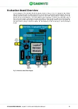
The WRHML37XEVBX Evaluation Board is designed to allow easy development of Lepton
9
R9100C
applications using a PC or other hosts capable of generating easy2read
©
traffic over UART. It includes
several integrated circuit components and connectors to allow connection to USB or UART hosts, or other
development kits or customer hardware. These components are shown in
Evaluation Board Key Components. Components on the backside are shown with dotted lines. This section
describes these components and connectors in detail.
Fig. 5.3: WRHML37XEVBX Evaluation Board Key Components
Integrated Circuit Component Descriptions
ZZ1 is the Lepton
9
R9100C RAIN RFID reader module. It is a completely integrated Gen2 UHF RFID reader,
requiring only power, RF, and UART connections to read and write tags. It is in a 29 by 32 mm surface
mountable package.
U1 is the RF switch IC that is used to switch between the two antenna options: the onboard surface mount
(SMT) antenna ANT1, and the SMA antenna port J2.
ANT1 is a surface mounted far field fractal antenna for RAIN (UHF) RFID (Ignion NN01-105). It uses the
ground plane of the evaluation board to form a read zone near the board.
The RF switch IC is controlled by a single input which is connected to the center pin of the antenna
selection jumper J1. Removing the jumper causes the switch to connect the Lepton
9
R9100C
’s RF port t
o
the SMT antenna A1. Installing the jumper in the leftmost position selects the SMA connector J1. Installing
the jumper in the rightmost position allows the Lepton
9
R9100C to select the antenna using GPIO1. In the
default low state, the SMA connector J1 will be selected. In the high state, the SMT antenna ANT1 will be
selected. The antenna can be controlled dynamically, please refer to the easy2read
©
SDK documentation.
The RF switch IC is a Peregrine PE42422.
U3 and U4 are the USB-UART ICs. They allow an USB host to communicate with the Lepton
9
R9100C module
via 3.3 volt UART. U3 connects to the host serial interface (UART1) via the micro USB connector J4.
U4 connects to the debug serial interface (UART2) via the micro USB connector J6. Both will be presented
on a host as connection options. On a windows PC, they will be shown COM ports. On a linux PC, they will
appear as /dev/ttyUSB<X>. The USB-UART IC is the Microchip MCP2200-I/MQ.
U5 is the 3.3 volt linear regulator IC for the USB-UART ICs. The USB-UART ICs require an external voltage
source to specify the logic level of the UART interface. This IC supplies that voltage reference and supply.
The voltage regulator IC is a Texas Instruments TPS73533DRVR.
U2 is the IO LED buffer IC. This buffer allows high current drive for the on-board GPIO LEDs DL2-DL7, which
indicate the GPIO and Health and Status pin states. Without the buffer, the LEDs would load the IOs, and
reduce the potential current supply available to custom hardware attached to the IOs. The buffer IC is a TI
74HC4050.


