


- 13 -
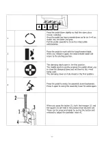
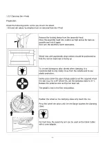
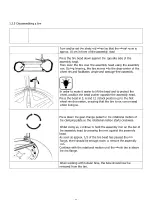
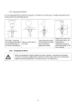
Check whether the assembly head is in the correct position for the
wheel rim. If necessary, set it up as described in the subsection
“Setting up the assembly
head”.
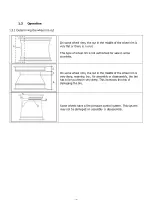
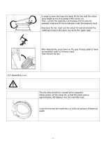
Now place the tire on the wheel rim at an angle so that the
assembly head does not touch any parts of the tire when
swiveling.
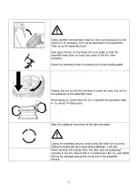
Swivel the assembly tower by pressing the corresponding pedal.
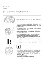
Position the tire so that the tire bead is under the nose, but still on
the guideway of the assembly head.
When doing so, ensure that the tire is opposite the assembly head
in the wheel rim depression.
Start the rotational movement of the clamping plate.
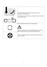
During the assembly process, ensure that the bead run is correct.
Failing to ensure this can cause serious damage to the tire.
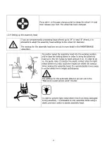
When working with tubular tires, the tube must be positioned
correctly in the tire. Ensure that it is positioned in the tire such that it
will not be damaged during the remainder of the assembly
process.
Summary of Contents for 2765
Page 1: ...OPERATING INSTRUCTIONS CAE 2765 2725 Tire Changer...
Page 3: ...3...
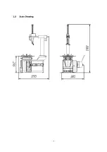
Page 17: ...17 1 5 Scale Drawing...
Page 34: ...34...
Page 35: ...35 6 1 Pneumatic circuit diagram 6 0 APPENDIX...
Page 36: ...36 6 2 Electric circuit diagram...
Page 37: ...37 6 3 Hydraulic circuit diagram Not relevant...


