- 11 -
1.3.5
Disassembling a tire
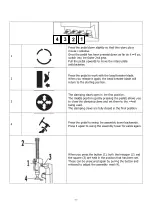
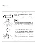
Turn and/or set the stretched wheel so that the wheel valve is
approx. 10 cm in front of the assembly head
Press the tire bead down against the opposite side of the
assembly head.
Then lever the tire over the assembly head using the assembly
iron. During levering, the tire moves into the drop-center of the
wheel rim and facilitates simple and damage-free assembly.
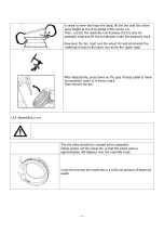
In order to make it easier to lift the bead and to protect the
wheel, position the bead pusher opposite the assembly head.
Press the bead in 3, 6 and 12 o’clock position up to the first
wheel rim depression, ensuring that the tire is not compressed
whilst doing so.
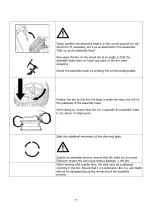
Press down the gear change pedal for the rotational motion of
the clamping plate so the rotational motion starts clockwise.
Whilst doing so, continue to hold the assembly iron on the bar of
the assembly head by pressing the iron against the assembly
head.
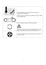
As soon as approx. 1/3 of the tire bead has passed the rim
flange, there should be enough room to remove the assembly
iron.
Continue with the rotational motion until the whole tire is above
the rim flange.
When working with tubular tires, the tube should now be
removed from the tire.
Summary of Contents for 2765
Page 1: ...OPERATING INSTRUCTIONS CAE 2765 2725 Tire Changer...
Page 3: ...3...
Page 17: ...17 1 5 Scale Drawing...
Page 34: ...34...
Page 35: ...35 6 1 Pneumatic circuit diagram 6 0 APPENDIX...
Page 36: ...36 6 2 Electric circuit diagram...
Page 37: ...37 6 3 Hydraulic circuit diagram Not relevant...

