background image


  Setup Guide


905K540252v3


Setting Up the Large Monitor 


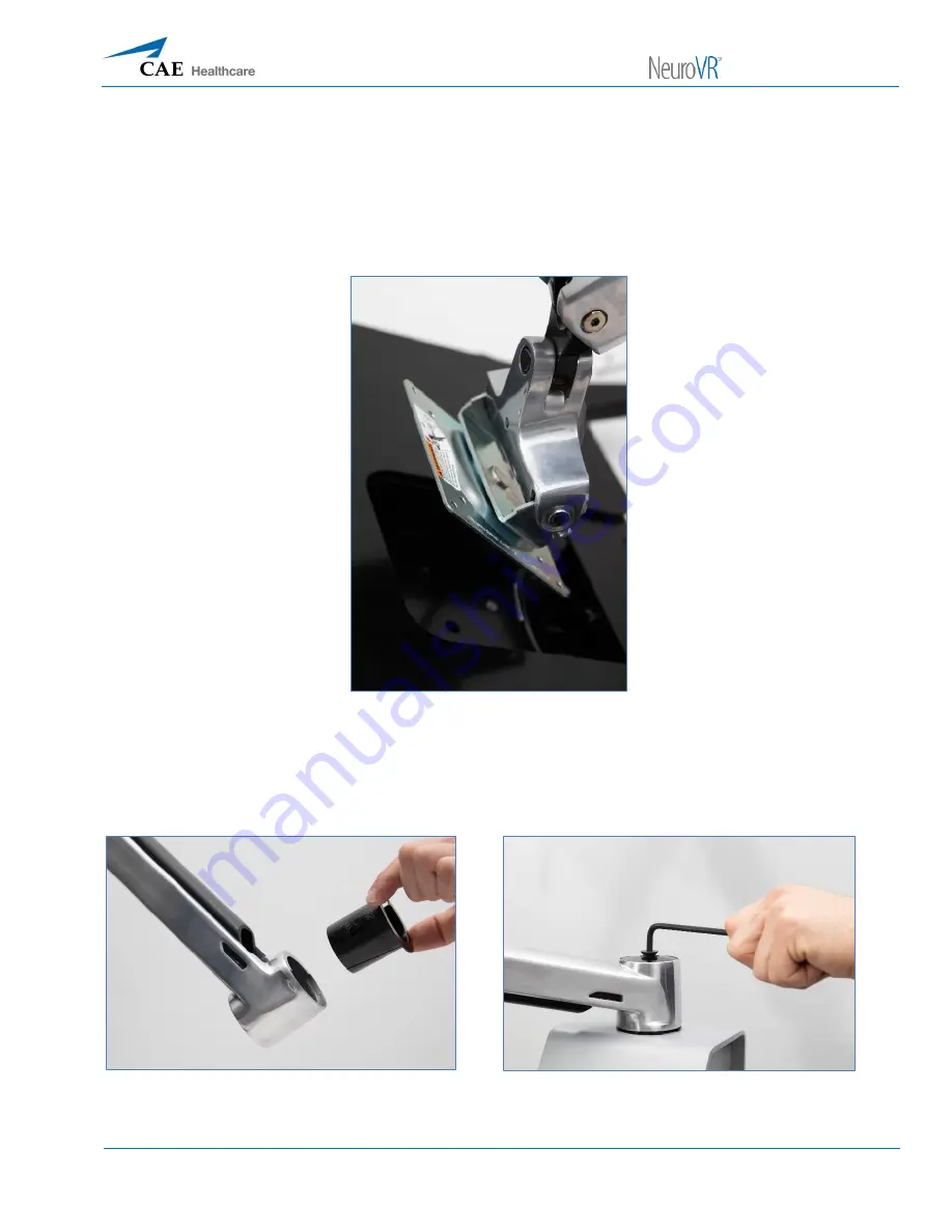
Remove monitor and monitor arm 


Attach the arm to the monitor using the 4 screws 


Secure monitor to arm


Connect monitor arm to the NeuroVR base with 3/16th Allen wrench (be sure to add the bushing to 
avoid scratching the unit) 


Place bushing into arm


Tighten with Allen wrench


Summary of Contents for NeuroVR

Page 1: ...Setup Guide 905K540252v3 1 Setup Guide...

Page 2: ...Setup Guide 2...

Page 3: ...Setup Guide 905K540252v3 3 This guide will help you unpack and setup the NeuroVR simulator Removing Items from the Crate Remove all 6 screws from the front panel NeuroVR shipping crate...

Page 4: ...Setup Guide 4 Remove all the foam from around the NeuroVR Unlock the wheels Using the door as a ramp wheel out the NeuroVR base Use the front panel as the ramp...

Page 5: ...uide 905K540252v3 5 Remove the Stereoscope box arm accessory box and head from the top of the crate Stereoscope box opened Remove styrofoam to access Unwrap all parts and accessories All included acce...

Page 6: ...Setup Guide 6 Attaching the Neck Assembly Pull all cables out Insert the neck into the NeuroVR base Insert the neck...

Page 7: ...Setup Guide 905K540252v3 7 Tighten the 6 wing nuts to secure the neck Secure the wing nuts...

Page 8: ...Setup Guide 8 Add the back panel of the neck with the 4 screws provided Back panel location Secure the screws Feed the wires through the grommet hole...

Page 9: ...onitor and monitor arm Attach the arm to the monitor using the 4 screws Secure monitor to arm Connect monitor arm to the NeuroVR base with 3 16th Allen wrench be sure to add the bushing to avoid scrat...

Page 10: ...Setup Guide 10 Connect the 4 cables from the NeuroVR base to the large monitor Connect the cables Completing the Final Setup Remove foam from the 2 haptic units Remove the foam cover...

Page 11: ...Guide 905K540252v3 11 Plug in the keyboard Plug in keyboard Adjust the arm rest see Adjustable Armrest section of the user guide pg 5 Tilt the small touchscreen monitor forward Tilt the touchscreen mo...

Page 12: ...Setup Guide 12 Insert tray holders in the NeuroVR and add trays Insert tray holders Add trays...

Page 13: ...Setup Guide 905K540252v3 13 Remove pedals from the foot pedal holder Place foot pedals Take power cord out of the base and plug it in at the back Cord stored in base...

Page 14: ...Africa Monday Friday from 8 00 a m to 5 00 p m CET Phone 49 0 6131 4950354 Email international service cae com Customer Service United Kingdom and Ireland Monday Friday from 9 00 a m to 5 00 p m GMT P...

Page 15: ...by loosening the 4 screws from the grey metal back panel of the NeuroVR base Note To avoid damaging product or voiding warranty do not attempt to repair NeuroVR without customer service assistance Rem...

Page 16: ...different components of the simulator and allow it to function correctly Under the guidance of NeuroVR Support these connections may be accessed and verified Main components of the control box The fol...

Page 17: ...To verify that your cable is connected and you have quick access to the circuit board 1 Tilt the small monitor up 2 Remove the grommet cover 3 Verify all cables are connected to the circuit board Veri...

Reviews: