background image

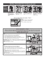
Wiring Instructions - Part 1

INSTALLATION INSTRUCTIONS

Wiring Instructions - Part 2

BTF1


240/208  
Volt 
Application

BTF1


120 Volt 
Application

BTF2


240/208  
Volt 
Application

GROUND 

SCREW

GROUND 

SUPPLY

GROUND 

SCREW

GROUND 

SCREW

GROUND 

SCREW

GROUND 

SCREW

GROUND 

SCREW

GROUND 

SCREW

GROUND 

SCREW

GROUND 

SCREW

GROUND 

SCREW

1. All electrical work and materials must comply 
with the National Electric Code (NEC), the Occu-
pational Safety and Health Act (OSHA), and all 
state and local codes.
2. Use copper conductors only.

3. Turn off power to heater circuit at main discon-
nect panel.
4. Connect grounding lead to grounding screw 
provided.

STEP 1

Turn the electrical power off at 
the circuit breaker or fuse box.

STEP 2

Remove the junction box cover 
at the end of the baseboard you 
wish to wire.

STEP 3

Connect the supply grounding 
wire to the green grounding 
screw provided.

STEP 4

Disconnect one factory connector 
on the side you have open, 
leaving two loose heater wires. 

IMPORTANT: If wiring on the 

left side, disconnect ONLY 

ONE factory connector!

A. 

Connect a hot supply wire to the red 

thermostat wire.

B. 

Connect the black thermostat wire to 

one of the heater wires.

C. 

Connect the remaining hot supply 

wire to the remaining heater wire.

Proceed to Part 3.

A. 

Connect the hot supply wire to the 

red thermostat wire.

B. 

Connect the black thermostat wire to 

one of the heater wires.

C. 

Connect the neutral supply wire to 

the remaining heater wire.

Proceed to Part 3.

A. 

Connect the black thermostat wires 

to the loose heater wires. 

B. 

Connect the hot supply wires to the 

red thermostat wires.

Proceed to Part 3.

STEP 5

Refer to the instructions in Part 2 that correspond to your thermostat application.

Page 2

Summary of Contents for BTF1

Page 1: ...ate any heater after it malfunctions Disconnect power at service panel and have heater inspected by a qualified electrician before reusing 4 To disconnect heater turn controls to off and turn off powe...

Page 2: ...d of the baseboard you wish to wire STEP 3 Connect the supply grounding wire to the green grounding screw provided STEP 4 Disconnect one factory connector on the side you have open leaving two loose h...

Page 3: ...wire is required Important When wiring multiple heaters to one thermostat the baseboards must be in the same room Maximum amperage rating 25 amps BTF1 1 Disconnect one factory connector on each baseb...

Page 4: ...STALLATION OF REPLACEMENT PARTS DOES NOT MODIFY OR EXTEND THE UNDERLYING WARRANTIES REPLACEMENT OR REPAIR OF ANY CADET PRODUCT OR PART DOES NOT CREATE ANY NEW WARRANTIES 8 These warranties give you sp...

Page 5: ...e la alimentaci n en el panel de servicio y haga que lo inspeccione un t cnico el ctrico calificado antes de volver a utilizarlo 4 Para desconectar el calentador gire los con troles a la posici n de a...

Page 6: ...l cortacircuito o en la caja de fusibles PASO 2 Retire la cubierta de la caja de empalmes en el extremo del z calo que desea cablear PASO 3 Conecte el alambre de puesta a tierra del suministro al cabl...

Page 7: ...igos nacionales y locales Se requiere alambre adicional Importante Al cablear m ltiples calentadores a un termostato los z calos deben estar en la misma habitaci n Amperaje nominal m ximo 25 amperios...

Page 8: ...arant as le otorgan derechos legales espec ficos y es posible que usted tenga otros derechos que var en de un estado a otro Cadet no asume ni autoriza a nadie que lo haga en su nombre ninguna otra obl...

Reviews: