background image

16

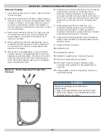
Chimney Connector And Draft Regulator

•  Venting the boiler requires 6” diameter chimney 

connector pipe and use of manufacturer provided draft 

regulator.

•  Regulator, when properly installed, automatically 

controls the draft. 

•  Install in horizontal section of pipe, may also be 

installed in angled or vertical section of pipe. 

•  Verify “top” of regulator is at the top and short pipe 

section which holds the vane is horizontal. 

•  Even though locating draft regulator close to chimney 

reduces noise, 

install draft regulator as close as 

practicable to the boiler.

•  Install chimney connector, start at boiler with vertical 

pipe, elbow, then install draft regulator horizontally.

•  When regulator is in place, start at chimney and work 

back to the regulator. 

•  Join the two sections with draw-band. 
•  Horizontal pipe must slope up toward the chimney at 

least 1/4 inch per linear foot of venting. 

•  Chimney connector must not leak and must be 

fi

 rmly 

supported. 

•  Join each section with at least two sheet metal screws. 

Support every second section with a stovepipe wire.

 NFPA RECOMMENDED MINIMUM CHIMNEY SIZES

FIRING RATE

(gph)

CHIMNEY

HEIGHT (ft)

NOMINAL

CHIMNEY

ROUND 

LINER INSIDE

SQUARE 

LINER INSIDE

0.60 - 1.30

15

8” x 8”

6”

6 ¾” x 6 ¾”

1.31 - 1.80

15

8” x 8”

7”

6 ¾” x 6 ¾”

1.81 - 2.00

20

8” x 8”

8”

6 ¾” x 6 ¾”

For elevations above 2,000 feet above sea level, add 3 feet to the chimney heights.

CHIMNEY AND CHIMNEY CONNECTIONS

For oil 

fi

 red boilers for connections to vents or chimneys, 

vent installations shall be in accordance with applicable 

provisions of INSTALLATION OF OIL BURNING EQUIPMENT, 

NFPA31  latest revision, and applicable provisions of local 

building codes.

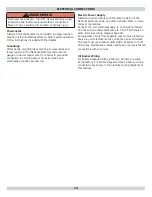
NOTICE

Fresh air (ventilation) is important to proper 

venting. Ventilation and venting are two parts of the 

same system. Inadequate ventilation will result in 

inadequate venting. Always be sure to have enough 

ventilation to support proper venting.

Check your chimney to make certain that it is right size, 

properly constructed and in good condition.

See Table “Recommended Minimum Chimney Sizes”. 

For additional chimney design and sizing information, 

consult the National Standard for Chimneys, Fireplaces, 

Vents and Solid Fuel Burning Appliances, ANSI/NFPA 211.

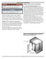
WARNING

Fire Hazard.  Maintain minimum vent pipe clearance 

of 18” from surface of vent to wood and other 

combustible materials. Failure to comply may result 

in death or serious injury.

!


Summary of Contents for BW4BAH-91

Page 1: ...0 BW4RAH 140 BW5BAH 140 BW5RAH 140 BW4BAH 126 BW4RAH 126 BW5BAH 126 BW5RAH 126 BW4BAH 175 BW5RAH 175 BW5BAH 175 BW5RAH 175 BW4BAH 210 BW4RAH 210 BW5BAH 210 BW5RAH 210 Models Series C BW4BAH 168 BW4RAH...

Page 2: ...fety relief valve drain valve flue brush and extra boiler tap for expansion tank or air elimination SAFETY NOTICES Boiler installation shall be completed by qualified agency NOTICE Used to address pra...

Page 3: ...183 84 3 5 13 7 21 6 11 Mbh 1 000 BTU per hour BTU British Thermal Unit Heating Capacity based on 13 CO2 with a 0 02 w c draft over fire and a 1 smoke or less Testing was done in accordance with the...

Page 4: ...es of steam and hot water which may damage the surroundings Before installing the safety relief valve read the manufacturer s instructions and maintenance section of the manual on safety relief valves...

Page 5: ...where passage is required for access to another side for cleaning servicing inspection or replacement of any parts that normally may require such attention Boilers must be installed at least 6 from co...

Page 6: ...IRCULATING PUMP IN RETURN LINE OR AFTER THE EXPANSION TANK SHUT OFF VALVE OIL FILTER OIL LINES FOUNDATIONS TO OUTSIDE LINES TO OTHER APPLIANCES SERVICE LINE OVERCURRENT PROTECTED SAFETY SWITCH 2 FILL...

Page 7: ...ts the criteria for unconfined space Total input of all combustion equipment installed in combined space shall be considered in making this determination Each opening shall have minimum free area of o...

Page 8: ...he enclosure 3 When communicating with outdoors through horizontal ducts each opening shall have minimum free area of one square inch per 2 000 Btu per hour of total input rating of all equipment in t...

Page 9: ...ler See figure 6a A Install safety relief valve with spindle in vertical position B Do not install shutoff valve between boiler and safety relief valve C Install discharge piping from safety relief va...

Page 10: ...emperatures of less than 120 F Condensation is corrosive and can eventually cause damage to boiler and venting system Minimum design return water temperature to prevent this condensation in boiler and...

Page 11: ...M EXPANSION TANK NOTE CIRCULATORCANALSOBEINSTALLED ON RETURN PIPING PIPING ARRANGED FOR POWER PURGING AIR OUT OF SYSTEM PIPING REFER TO THIS MANUAL S SECTION ON FILLING THE SYSTEM WITH WATER OPTION 1...

Page 12: ...MPS AWAY FROM EXPANSION TANK PIPING ARRANGED FOR POWER PURGING AIR OUT OF SYSTEM PIPING REFER TO THIS MANUAL S SECTION ON FILLING THE SYSTEM WITH WATER OPTION 1 SYSTEM PIPING Figure 9 System Piping Ar...

Page 13: ...ON SUPPLY PIPING PUMPS AWAY FROM EXPANSION TANK PER THIS MANUAL USE OPTION 2 IN FILLING THE SYSTEM WITH WATER THIS PIPING ARRANGEMENT CAN BE USED WITH ZONE VALVES OR ZONE CIRCULATORS SYSTEM PIPING Fig...

Page 14: ...ine controls are used Tankless coils are meant to provide domestic hot water for intermittent draws not continuous flow NOTICE Do not use tankless coil if your water is excessively hard with lime or o...

Page 15: ...mption Tankless coil performance will fall as concentration of antifreeze is increased Refer to boiler and piping water volumes tables BOILER WATER VOLUMES Number of Boiler Section Total Volume Gallon...

Page 16: ...SIZES FIRING RATE gph CHIMNEY HEIGHT ft NOMINAL CHIMNEY ROUND LINER INSIDE SQUARE LINER INSIDE 0 60 1 30 15 8 x 8 6 6 x 6 1 31 1 80 15 8 x 8 7 6 x 6 1 81 2 00 20 8 x 8 8 6 x 6 For elevations above 2 0...

Page 17: ...Connection Minimum height Must be at least 3ft 9m higher than highest part of passage through roof Must be at least 2ft 7m higher than any neighboring object within 10ft 3m Must have unobstructed top...

Page 18: ...regulations Connect 115 volt electrical supply to L1 and L2 terminals on limit and two thermostat wires to T and T terminals on same limit See wiring diagram page 28 Run separate circuit from separate...

Page 19: ...ing drain valve runs air free close isolation valve or zone valve Repeat this procedure for remaining heating zones D Once all zones are filled with water and purged of air close power purging drain v...

Page 20: ...r must be installed in fuel unit Refer to fuel unit instructions furnished with burner for specific instructions on installing bypass plug Do not exceed fuel unit manufacturer s recommendations for ru...

Page 21: ...175 1 00 80 A 1 25 F6 1 NO 10 0 3 AFG F HEAD 140 BW 4 5 BAH 210 1 25 80 A 1 50 F6 1 NO 10 2 3 AFG F HEAD 140 BW 4 5 BAH 168 1 00 60 B 1 20 0 NO 10 1 5 2 AFG 50 MD 140 BW 4 5 BAH 245 1 50 45 B 1 75 2...

Page 22: ...22 OPERATING THE BOILER Figure 13 Burner Adjustments and Settings...

Page 23: ...e unit is full of vapor or when the combustion chamber is very hot Locate thermostat five feet above the floor on inside wall Locate thermostat to sense average room temperature avoid the following TH...

Page 24: ...ent that may lodge on valve seat Permit valve to snap shut Refer to valve manufacturer s instructions packaged for more details Conventional Expansion Tank Tank may become water logged or may receive...

Page 25: ...tions from combustion chamber area take care to not damage any of refractory or blanket insulation To gain access to combustion chamber first check that shut off valve on fuel oil line is closed and d...

Page 26: ...assembly make sure head location and size if applicable are per manufacturer s recommendations If burner being used has damaged head replace head with same head recommended for use on this boiler 6 In...

Page 27: ...k to be sure electric power supply circuit is ON Controls out of adjustment Reset according to instructions Radiators not heating Open radiator vents to excess air Check flow control valve if used It...

Page 28: ...28 ELECTRICAL WIRING Figure 16 Honeywell L7248L Control With Beckett AFG Burner...

Page 29: ...29 Figure 17 Honeywell L7248L Control With Riello F5 F10 Burner ELECTRICAL WIRING...

Page 30: ...burner fan motor to pre purge combustion chamber and oil pump to bring supply oil pressure up to its set point helping to provide clean light off LIMIT CONTROL provided Refer to manufacturer instructi...

Page 31: ...NOTES...

Page 32: ...CAC BDP 7310 West Morris St Indianapolis IN 46231...

Reviews: