10
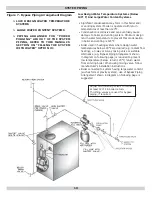
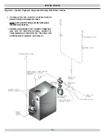
Adjust two throttling valves to maintain
at least 120°F in boiler return.
Throttling valves are used for bypass
piping, if required.
> LOW DESIGN WATER TEMPERATURE
SYSTEMS
> LARGE WATER CONTENT SYSTEMS
> PIPING ARRANGED FOR “POWER
PURGING” AIR OUT OF THE SYSTEM
PIPING, REFER TO THIS MANUAL’S
SECTION ON “FILLING THE SYSTEM
WITH WATER” OPTION #1
SYSTEM PIPING
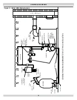
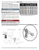
Figure 7 - Bypass Piping Arrangement Diagram
Low Design Water Temperature Systems (Below
140° F) And Large Water Content Systems
• Signi
fi
cant condensation may form in this boiler and/
or venting system if boiler is operated with return
temperatures of less than 120°F.
• Condensation is corrosive and can eventually cause
damage to boiler and venting system. Minimum design
return water temperature to prevent this condensation
in boiler and venting is 120°F.
• Boiler used in heating system where design water
temperatures below 140°F are desired (e.g. radiant
fl
oor
heating), a 3-way or 4-way mixing valve or suitable
alternative (e.g. Bypass Piping Arrangement shown
in diagram on following page) is required to prevent
low temperature (below return 120°F) return water
from entering boiler. When using mixing valve, follow
manufacturer’s installation instructions.
• Boiler connected to system having large water content
(such as former gravity system), use of Bypass Piping
Arrangement shown in diagram on following page is
suggested.
Summary of Contents for BW4BAH-91
Page 22: ...22 OPERATING THE BOILER Figure 13 Burner Adjustments and Settings...
Page 28: ...28 ELECTRICAL WIRING Figure 16 Honeywell L7248L Control With Beckett AFG Burner...
Page 29: ...29 Figure 17 Honeywell L7248L Control With Riello F5 F10 Burner ELECTRICAL WIRING...
Page 31: ...NOTES...
Page 32: ...CAC BDP 7310 West Morris St Indianapolis IN 46231...


