


17
Y
C
R
O
L2
L1
2
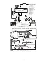
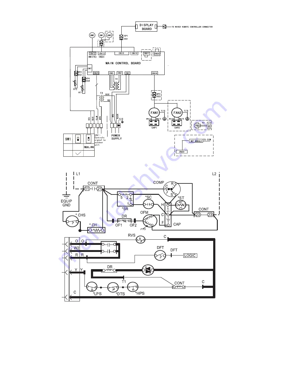
Notes :
1.To be w ired in acco rdance with Natio nal
Electr ic N.E .C. a nd local cod es.
2.Use Copp er con ductors onl y.
Use c onductors s uitable for at lea st 75° C(167 °F).
3. If a ny of the original wires , as s upplied
must be re place d, use the s ame o r equivalent wire.
Legen d:
................
Model spec ific fe ature
CAP: Capac itor
CN 1:
CN 2/ 3: Tr ansfor mer
CN 25 :Contr ols
signal interface(R /C)
CN 7: Sens or
Live w ire L1 /Null line L2
interface
24V
interface
CN 20 : Netw ork module interface
CN 12 : Ver tical s wing motor interface
CN 13 : horiz ontal s wing motor interface
CN 10 : Disp lay bo ard interface
CN 15 : Sign al interface( Y/O)
CN 1 1: Wa ter lev el dete ction s witch
CN 16 : Motor inte rface
RT1: Room temperature sens or
RT2: Pipe t emperature senso r
T3/4 : Trans former
GM1/3 : Leve l swin g motor
GM 2: Vert ical s wing motor
XS/XP : Con nectors
1
O N
1
O N
O N
FACTORY
SETTING
FACTORY
SETTING
MODE
MODE
F L O O R
F L O O R
Fig. 34 – 40MKQB**F wiring diagram
OUTDOOR UNIT SCHEMATIC DIAGRAM
Fig. 35 – 25HHA4/224ANS Wiring Diagram


