5-2 SmartSwitch 6500 Installation and Setup Guide
Front Panel
Specifications
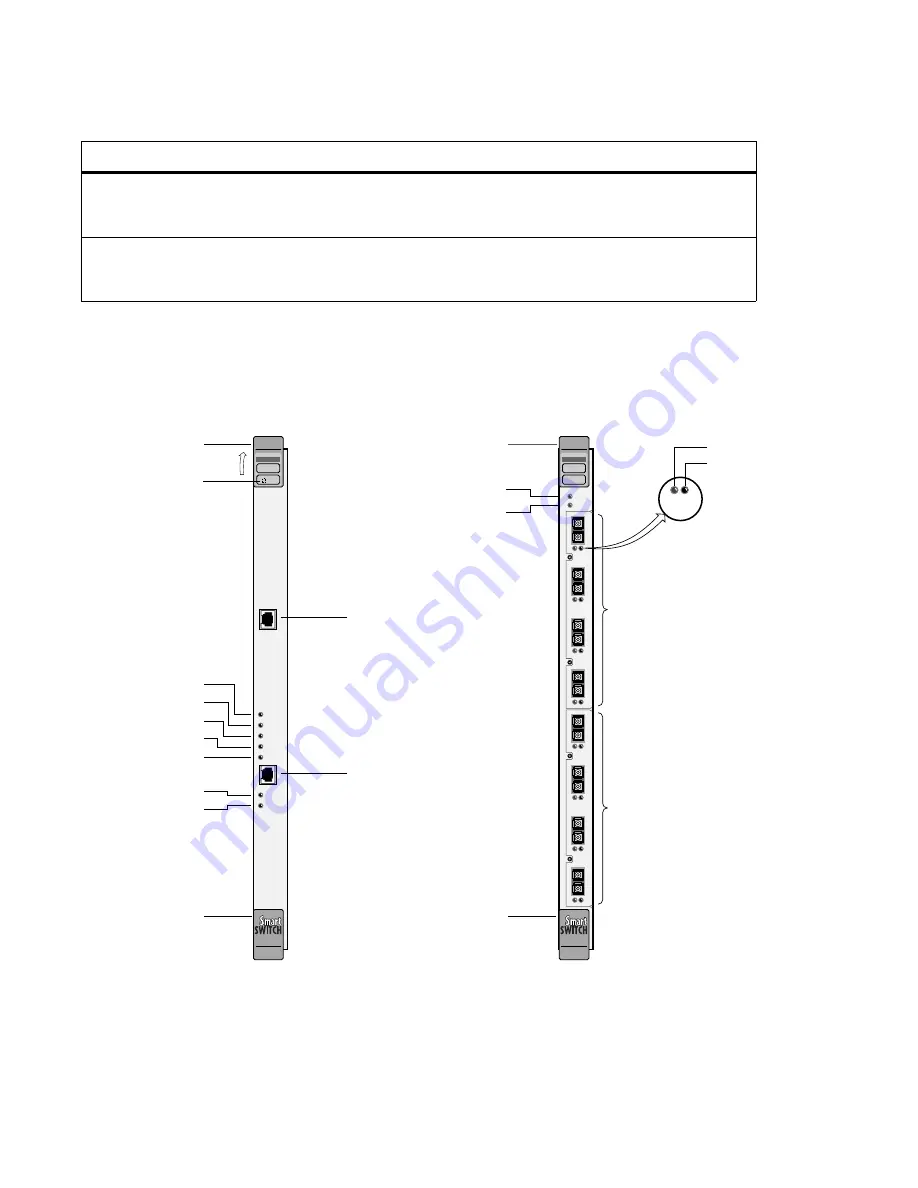
Figure 5-1 CSM and TSM LEDs
DATA
Normally flashing when
connected, data is
passing through the port
No data is passing
through port.
NO SYNC
Framer is not receiving
sync
Normally off when
connected, Framer
is receiving sync
*
Slave TSM/CPU
Table 5-2
TSM LEDs (Continued)
LED
Green
Amber
Red
Unlit
ATM
COM
ENET
POWER
ACTIVE
STANDBY
FAIL
ENET RDY
TX DATA
RX DATA
CSM
Console Terminal
(RJ-45)
Ethernet Port
(10Base-T)
POWER
ACTIVE
STANDBY
FAIL
ENET RDY
TX DATA
RX DATA
Reset Button
Ejector
Ejector
(Ethernet interface ready)
ATM
FAIL /MODE
CPU
FAIL/ OK
TSM
NO SYNC
D
ATA
123
4
6A-IOM-21-4
NO SYNC
D
ATA
123
4
6A-IOM-21-4
B
TSM
NO SYNC
DATA
I/O Module
I/O Module
NO SYNC
D
ATA
Ejector
TSM FAIL / OK
CPU FAIL / MODE
Ejector
Summary of Contents for SmartSwitch 6500
Page 12: ...xii SmartSwitch 6500 Installation and Setup Guide List of Figures...
Page 14: ...xiv SmartSwitch 6500 Installation and Setup Guide List of Tables...
Page 18: ...1 4 SmartSwitch 6500 Installation and Setup Guide SmartSwitch 6500 Modules Introduction...
Page 54: ...4 12 SmartSwitch 6500 Installation and Setup Guide Managing Your ATM Network ATM Administrator...
Page 60: ...5 6 SmartSwitch 6500 Installation and Setup Guide Technical Specifications Specifications...


