


– 4 –
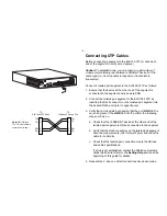
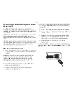
Connecting UTP Cables
Before connecting a segment to the ELS100-16TX, check each
end of the segment to verify wire crossover.
Connect a twisted pair segment to the ELS100-16TX as follows:
1. Ensure that the device at the other end of the segment is
connected to the segment and is powered ON.
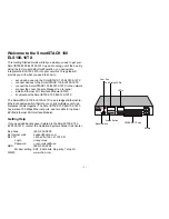
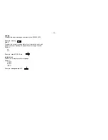
2. Connect the twisted pair segment to the ELS100-16TX by
inserting the RJ45 connector on the twisted pair segment into
the desired RJ45 port (refer to upper figure).
3. Verify that a Link exists by checking that the port
LINK
LED is
on (solid green). If the
LINK
LED is off, perform the following
steps until it is on:
a. Check that the 100BASE-T device at the other end of the
twisted pair segment is ON and connected to the segment.
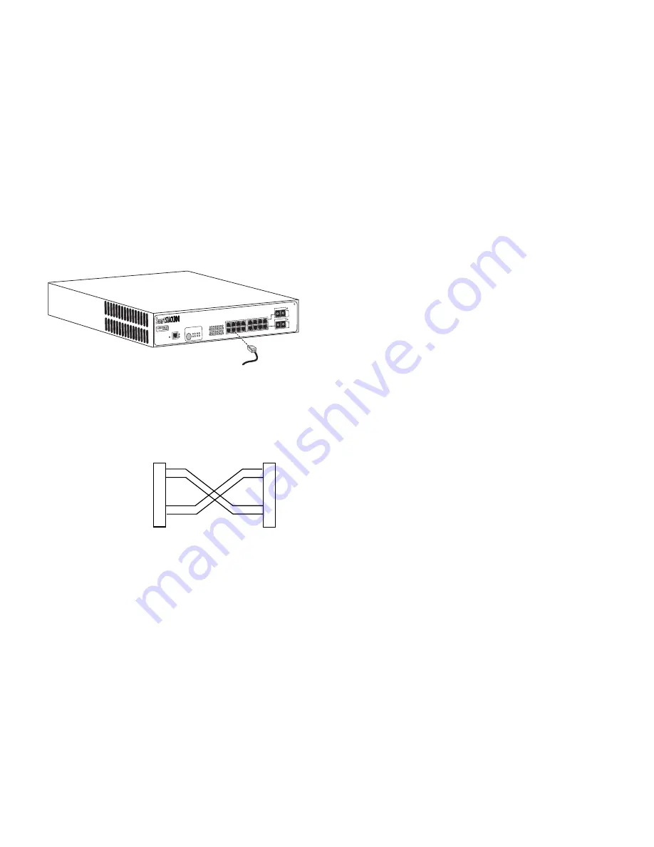
b. Verify that the RJ45 connectors on the twisted pair segment
have the proper pinouts (refer to lower figure) and check the
cable for continuity.
c. Check that the twisted pair connection meets the dB loss
and cable specifications.
If a link is not established, contact the Cabletron Systems
Global Call Center. Refer to the
Getting Help
section at the
beginning of this guide
for details.
4. Repeat step 2, above, until all connections have been made.
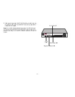
PWR
CPU
RESET
COM
PORT STATUS MODE
TX ACT FDX
MON
RX COL 100
USR
STATUS
EPIM100
EPIM100
10X 12X 14X 16
X
9X 11X 13X 15
X
2X 4X 6X 8x
1X 3X 5X 7X
LINK
STATUS
LINK
STATUS
2 4 6 8
10 12 14 16
1 3 5 7
9 11 13 15
ELS100-16TX
1
2
3
6
1
2
3
6
TX+
TX-
RX+
RX-
TX+
TX-
RX+
RX-
TO
ELS100-16TX RJ-45
TO
100Base-T Device Port
Note: RX+/RX- and
TX+/TX- must share a
common color pair.
Caution:
To establish a link, you must have an odd number of
crossovers (preferably one) between 10BASE-T devices of the
same type (i.e., from repeater to repeater or transceiver to
transceiver).


