background image

Chapter 3: Installing the IRM3

Page 3-6

IRM3 User’s Guide

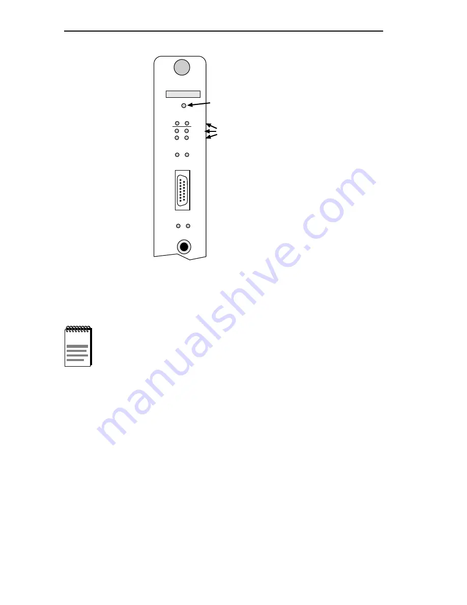
Figure 3-3

LANVIEW LEDs

NOTES

When the IRM3 is first powered up, the AUI port acts as the 
repeater port and the Fiber ports are off. This configuration can 
be altered using IRM3 Local Management or network 
management tools so that the Fiber ports act as the repeater 
port and the AUI port is off.

Powering off the IRM3 or using the Reset switch will not alter 
the Repeater port settings if the battery back-up is enabled. For 
further information, refer to the discussion of Port Association 
in Chapter 4.

IRM3

SN

RESET

 PWR             BOK

 MGMT             RCV

 CLN              POK

A

  ON             PWR

  ON             LNK

T
X

F

O

U

I

0494106

RESET SWITCH

LANVIEW LEDS

Summary of Contents for IRM-3

Page 1: ...IRM3 INTELLIGENT REPEATER MODULE USER S GUIDE A U I T X R X ON LNK ETHERNET IRM3 SN PWR ON PWR BOK MGMT RCV POK CLN RESET U P S C O N S O L E F O I R L ...

Page 2: ...er ON FO Fiber Optic port is active repeater port LNK FO Link is established between port and Fiber Optic device CONNECTIONS AUI Port 15 pin D type receptacle Pin Signal Pin Signal Pin Signal 1 Logic Ref 6 Power Return 11 Logic Ref 2 Collision 7 No Connection 12 Receive 3 Transmit 8 Logic Ref 13 Power 12Vdc 4 Logic Ref 9 Collision 14 Logic Ref 5 Receive 10 Transmit 15 No Connection Console Modem P...

Page 3: ... 06 and above and for THN MIMs with part numbers below 9000043 06 9000043 06 and up Jumper over pins 2 and 3 Below 9000043 06 Jumper over pins 1 and 2 If using both set over 1 and 2 Jumper over pins 2 and 3 H6 and H8 Sets IRM3 console and modem ports for either internal signal generated by IRM3 or external signal generated by attached device Request to Send RTS and Clear to Send CTS signals Intern...

Page 4: ...ROFITS ARISING OUT OF OR RELATED TO THIS MANUAL OR THE INFORMATION CONTAINED IN IT EVEN IF CABLETRON SYSTEMS HAS BEEN ADVISED OF KNOWN OR SHOULD HAVE KNOWN THE POSSIBILITY OF SUCH DAMAGES Copyright 1996 by Cabletron Systems Inc P O Box 5005 Rochester NH 03866 5005 All Rights Reserved Printed in the United States of America Order Number 9030494 01 January 1996 SPECTRUM LANVIEW MicroMMAC and BRIM ar...

Page 5: ...G Changes or modifications made to this device which are not expressly approved by the party responsible for compliance could void the user s authority to operate the equipment DOC NOTICE This digital apparatus does not exceed the Class A limits for radio noise emissions from digital apparatus set out in the Radio Interference Regulations of the Canadian Department of Communications Le présent app...

Page 6: ...ment shall be interpreted and governed under the laws and in the state and federal courts of New Hampshire You accept the personal jurisdiction and venue of the New Hampshire courts EXCLUSION OF WARRANTY AND DISCLAIMER OF LIABILITY 1 EXCLUSION OF WARRANTY Except as may be specifically provided by Cabletron in writing Cabletron makes no warranty expressed or implied concerning the Program including...

Page 7: ... in all respects is proprietary data belonging to Cabletron and or its suppliers For Department of Defense units the product is licensed with Restricted Rights as defined in the DoD Supplement to the Federal Acquisition Regulations Section 52 227 7013 c 1 ii and its successors and use duplication disclosure by the Government is subject to restrictions as set forth in subparagraph c 1 ii of the Rig...

Page 8: ...2 2 2 2 The IRM3 in the Multi Media Access Center 2 3 2 2 1 Media Interface Modules 2 4 2 3 Sample Network Configuration 2 5 CHAPTER 3 INSTALLING THE IRM3 3 1 Unpacking the IRM3 3 1 3 2 Setting the IRM3 Jumpers 3 2 3 2 1 Setting the Battery Enable Disable Jumper H1 3 2 3 2 2 Setting the CTS External Internal Jumper H6 H8 3 3 3 2 3 Setting the THN MIM Jumper JP1 3 4 3 3 Installing the IRM3 into an ...

Page 9: ...e Enable Port Disable Port Option 4 14 4 4 6 Available Options from the Device Board Port Counters Screen4 14 4 5 Community Names Screen 4 15 4 5 1 Accessing the Community Names Screen 4 16 4 5 2 Community Names Screen Fields 4 16 4 5 3 Editing the Community Names Screen 4 17 4 6 The Setup Screen 4 18 4 6 1 Accessing the Setup Screen 4 19 4 6 2 Setup Screen Fields 4 19 4 6 3 Setting the Set IP Add...

Page 10: ... Reset Switch 5 5 5 4 Before Calling Technical Support 5 5 APPENDIX A SPECIFICATIONS A 1 Repeater Functionality A 1 A 2 AUI Port A 2 A 3 Fiber Optic Interface A 2 A 4 Console Port A 3 A 5 Microprocessors and Memory A 3 A 6 Environmental Requirements A 3 A 7 Agency Approvals A 4 A 8 Service A 4 A 9 Physical Properties A 4 INDEX ...

Page 11: ...It is assumed that you have a general working knowledge of Ethernet or IEEE 802 3 type data communications networks and their physical layer components This guide is organized as follows Chapter 1 Introduction describes the capabilities of the IRM3 including an explanation of the IRM3 repeater functionality and its management capabilities This chapter concludes with instructions on how to get help...

Page 12: ...d operating specifications for the IRM3 1 2 THE INTELLIGENT REPEATER MODULE IRM3 The Intelligent Repeater Module IRM3 Figure 1 1 is the heart of the Cabletron Systems Multi Media Access Center MMAC The IRM3 incorporates a high performance IEEE 802 3 repeater to allow maximum data paths between devices connected to the MMAC The IRM3 is Simple Network Management Protocol SNMP compliant and can be co...

Page 13: ...igent Repeater Module IRM3 IRM3 User s Guide Page 1 3 Figure 1 1 Intelligent Repeater Module IRM3 A U I T X R X ON LNK ETHERNET IRM3 SN PWR ON PWR BOK MGMT RCV POK CLN RESET U P S C O N S O L E 0494101 F O I R L ...

Page 14: ...tion to have the fiber port act as the repeater port and have the AUI port off This configuration allows you to connect the IRM3 to a fiber optic link segment directly without having to use an external fiber optic transceiver The IRM3 also provides the option through remote management to set one port as the active repeater port and the other port as a redundant repeater port Built into the front p...

Page 15: ...e by way of Cabletron Systems SPECTRUM Element Manager for Windows Thermal Sensors These sensors warn the management station if the IRM3 begins to overheat Ethernet SNMP Proxy With SNMP proxy you can use IRM3 remote management to control power settings for the American Power Conversion s uninterruptible power source UPS Connect the UPS to the IRM3 UPS port to control the power supply through an SN...

Page 16: ...RM3 can be controlled and managed by a variety of network management packages which include the following Cabletron Systems SPECTRUM Cabletron Systems SPECTRUM Element Manager for Windows Cabletron Systems IRM3 LM Local Management Third Party SNMP compliant Network Management Packages The IRM3 network management capabilities provide the necessary management tools for the IRM3 to operate at its ful...

Page 17: ...pecific information on in band management of the IRM3 refer to the applicable Network Management Package User s Manual 1 6 GETTING HELP If you need additional support related to the IRM3 or if you have any questions comments or suggestions related to this manual contact Cabletron Systems Technical Support By phone 603 332 9400 Monday Friday 8 A M 8 P M Eastern time By CompuServe GO CTRON from any ...

Page 18: ...k Revision level of firmware installed on all Cabletron Systems products The network load and frame size at the time of the failure if known Product history had the product been returned previously did it have the same problem etc The RMA number generated if any 1 7 DOCUMENT CONVENTIONS The following conventions are used throughout this document NOTE NOTE symbol Calls the reader s attention to any...

Page 19: ... used to supplement the procedures and other technical data provided in this manual The procedures will be referenced where appropriate but will not be repeated Cabletron Systems Multi Media Access Center Overview and Setup Guide Cabletron Systems IRM3 Management Module Guide for Microsoft Windows ...

Page 20: ...ecting network segments to the IRM3 you must follow the network guidelines listed below 2 1 1 802 3 Repeater Requirements Depending on the size of your network you may need to use multiple repeaters When planning your network keep in mind that 802 3 standards allow for no more than four repeaters in one data path If your network requires more than four repeaters use a bridge to create a new data p...

Page 21: ...er optic link segment should consist of one of the following 50 125 µm fiber optic cabling 62 5 125 µm fiber optic cabling 100 140 µm fiber optic cabling Attenuation The fiber optic cable must be tested with a fiber optic attenuation test set that is adjusted for an 850 nm wavelength This test verifies that the signal loss in a cable is within an acceptable level 13 0 dB or less for 50 125 µm fibe...

Page 22: ...IN THE MULTI MEDIA ACCESS CENTER The IRM3 is designed to be installed in a Cabletron Systems Multi Media Access Center MMAC network hub with the Flexible Network Bus FNB See Figure 2 1 The MMAC is fully protocol independent and is available in an eight slot MMAC M8FNB five slot MMAC M5FNB and three slot MMAC M3FNB model When installed in an MMAC the IRM3 supports 10 Mbps Ethernet IEEE 802 3 as wel...

Page 23: ...EEE 802 3 compatible medium attachment unit MAU ports which allows a direct connection to any type of media TPMIM 10BASE T Modules Cabletron Systems TPMIM 10BASE T modules are available with 12 or 24 ports equipped with DB9 RJ45 or RJ71 connectors for shielded unshielded twisted pair connections of up to 125 meters in length FOMIM Fiber Optic Modules Cabletron Systems FOMIM fiber optic modules are...

Page 24: ...GURATION The following illustrates a simple network configuration that provides a general idea of how the IRM3 can be used in a network Each workstation will have access to each other and the server through the TPMIM and the IRM3 The IRM3 manages the backplane and repeating functions between the users on the network The TPMIM provides access to the backplane for the workstations while the IRM3 rep...

Page 25: ...n checkout Connect to the network through either of the following AUI port Fiber Optic port Perform installation checkout Connect UPS if required 3 1 UNPACKING THE IRM3 Before installing the IRM3 visually inspect the module To unpack the module proceed as follows 1 Remove the shipping material covering the IRM3 in the shipping box 2 Carefully remove the module from the shipping box Leave the modul...

Page 26: ...e 3 1 allows you to enable or disable the Battery Back up for RAM on the IRM3 When set to the enabled position all parameters that you enter into the IRM3 will be saved if power to the MMAC should fail or if the IRM3 is removed from the MMAC When set to the disabled position all parameters entered into the IRM3 will be lost if power is removed from the IRM3 To set the Battery Enable Disable Jumper...

Page 27: ...SOLE port does not provide RTS or DTR the IRM3 must be configured to compensate internally for the lack of these signals In those situations the CTS External Internal jumpers H6 for the UPS port and H8 for the CONSOLE port allow the IRM3 to generate the CTS signal internally Refer to the Users Manual of the device to determine the requirements for this jumper setting H1 JP1 H2 H3 H4 H5 H8 H6 Batte...

Page 28: ...connector Set the THN MIM Jumper as follows If you are using THN MIM part numbers 9000043 06 and above in your MMAC place the jumper over pin 2 and pin 3 This is the position in which the IRM3 is shipped If you are using THN MIM part numbers 9000043 05 and below in your MMAC place the jumper over pin 1 and pin 2 3 3 INSTALLING THE IRM3 INTO AN MMAC CHASSIS The IRM3 is designed to be installed into...

Page 29: ...mately 2 seconds the LEDs should be in the following conditions PWR lit indicating that the IRM3 is receiving power POK lit indicating that the network interface chip associated with the IRM3 internal repeater ports have passed the internal loopback test and are now ready for transmission BOK lit indicating the IRM3 is operating properly WARNING Fill all open slots in the MMAC hub with blank plate...

Page 30: ... IRM3 Local Management or network management tools so that the Fiber ports act as the repeater port and the AUI port is off Powering off the IRM3 or using the Reset switch will not alter the Repeater port settings if the battery back up is enabled For further information refer to the discussion of Port Association in Chapter 4 IRM3 SN RESET PWR BOK MGMT RCV CLN POK A ON PWR ON LNK T X F O U I 0494...

Page 31: ...ending on which is the active repeater port 3 Connect the second workstation to the MIM using the appropriate transceivers and cable 4 Set the first workstation as the file server and the second as the client refer to the workstation documentation for setting up the workstations as file server and client When the workstations are properly set up proceed to send packets between the workstations and...

Page 32: ...3 4 Pre installation Test 3 5 CONNECTING THE IRM3 TO THE NETWORK This section provides procedures for connecting the IRM3 to the network using the AUI port or the Fiber Optic ports TPT Client Workstation File Server Workstation MMAC 3 FNB with IRM3 and TPMIM 0494109 ...

Page 33: ...UI cable no more than 50 meters in length to the transceiver 3 Attach the male connector on the AUI cable Figure 3 5 to the AUI port on the IRM3 4 Move the slide latchon the AUI port to secure it to the lock post on the AUI connector Figure 3 5 Connecting to the AUI Port CAUTION Be sure to disable the SQE test function on the transceiver you connect to the IRM3 AUI port Failure to do so will resul...

Page 34: ...evice Label the fiber optic cable to indicate which fiber is Receive and which is Transmit When you buy fiber optic cable from Cabletron Systems it is labeled so that at one end of the cable one fiber is labeled 1 and the other fiber is labeled 2 This pattern is repeated at the other end of the cable If you did not purchase your cable from Cabletron Systems be sure to label your cable in this mann...

Page 35: ...perform each of the following steps until it is a Check that the power is turned on for the device at the other end of the link b Verify that the fiber strands are properly crossed over between the IRM3 and the fiber optic device at the other end of the fiber optic link segment c Verify that the fiber cable meets the dB loss specifications outlined in Fiber Optic Port Requirements in Chapter 2 Sec...

Page 36: ...to move around to each node that is connected to the IRM3 Figure 3 7 You can verify the installation checkout by performing the following steps 1 Connect the server workstation to either a MIM using the appropriate cable and transceiver or to the IRM3 through either the AUI port using a transceiver and an AUI cable or to the Fiber Optic port using fiber optic cable 2 Going to each node connected t...

Page 37: ... UPS you can monitor and control the UPS through the IRM3 using SPECTRUM Element Manager for Windows To access UPS management from the IRM3 use a serial cable to connect the console port on the IRM3 to the 9 pin RS232 connector on the UPS Refer to the Cabletron Systems IRM3 Management Module Guide for Microsoft Windows for information on managing the UPS TPT Client Workstation File Server Workstat...

Page 38: ... emulation program or through a Hayes compatible modem To set up your terminal or Hayes compatible modem see Sections 4 1 or 4 2 respectively This chapter Explains how to access Local Management for the IRM3 through the CONSOLE port by using either a terminal or Hayes compatible modem Discusses the statistical information available concerning your IRM3 and its boards and ports Describes the Commun...

Page 39: ... s Guide Figure 4 1 shows the IRM3 LM screen flow Figure 4 1 IRM3 Local Management Screen Flow Enter Password IRM3 SNMP LOCAL MANAGEMENT INTRODUCTORY SCREEN DEVICE BOARD PORT COUNTERS SETUP COMMUNITY NAMES PORT ASSOCIATION TOKEN RING BOARD 0494111 ...

Page 40: ...configure your terminal console to communicate with Local Management Refer to your specific terminal manual for more instructions if necessary Table 4 1 lists the setup parameters necessary to configure your terminal console to communicate with Local Management If the terminal is a Digital Equipment Corporation VT320 terminal press F3 to access the Setup Directory If the local management terminal ...

Page 41: ...e Transmit XOFF any option Bits Parity 8 Bits No Parity Stop Bit 1 Stop Bit Local Echo No Local Echo Port DEC 423 Data Leads Only Transmit any option Auto Answerback No Auto Answerback Keyboard Setup Auto Repeat any option Keyclick any option Margin Bell Margin Bell Warning Bell Warning Bell Auto Answerback No Auto Answerback Table 4 2 9 pin to 25 pin Pinouts 9 Pin Male Connector IRM3 End to 25 Pi...

Page 42: ...assword The default password is the RETURN key Table 4 3 9 pin to 9 pin Pinouts 9 Pin Male Connector IRM3 End to 9 Pin Female Connector Terminal End Pin 3 Receive to Pin 3 Transmit Pin 2 Transmit to Pin 2 Receive Pin 5 Ground to Pin 5 Ground Pin 7 Request to Send to Pin 8 Clear to Send Pin 8 Clear to Send to Pin 7 Request to Send NOTE If the terminal you are using does not generate a Clear to Send...

Page 43: ...ctory Screen 6 Press RETURN The Device Board Port Counters screen Main shown in Figure 4 4 appears Refer to Section 4 4 for more information regarding this screen Local Management for the IRM3 is now ready for operation IRM3 SNMP LOCAL MANAGEMENT Cabletron Systems Incorporated P O Box 5005 Rochester NH 03867 5005 U S A 603 332 9400 IRM3 SNMP Version 0 00 xx C Copyright Cabletron Systems Inc 1992 M...

Page 44: ...low Control None Stop Bits 1 Modem Connected to the IRM3 Auto Answer On 4 2 2 Modem Attachment Cable Configuration Local Management is accessed by an RS232 cable available from Cabletron Systems This cable connects the modem to the IRM3 CONSOLE port The pin out for a cable with a 25 pin connector at the modem end of the cable and a 9 pin connector at the IRM3 end of the cable should be configured ...

Page 45: ... RETURN The IRM3 SNMP Local Management introductory screen shown in Figure 4 2 appears on the terminal 6 Press RETURN The Device Board Port Counters screen Main shown in Figure 4 4 appears Refer to Section 4 4 for more information on this screen Local Management for the IRM3 is now ready for operation NOTE If the modem you are using does not generate a Clear to Send CTS signal Request to Send RTS ...

Page 46: ...ccessing the local management screens of the IRM3 Figure 4 3 IRM3 Password Screen To access local management continue as follows 1 Enter your password The default password is the RETURN key NOTE If you have entered a Superuser name at the Community Names screen See Figure 4 5 the password will be the Superuser name If you have entered more than one Superuser name any of those names may be used as ...

Page 47: ...d ports You can see the number of bytes received the total number of packets the total number of receive and transmit collisions and the number of errors Figure 4 4 IRM3 Device Board Port Counters Screen 11 15 91 14 26 43 DEVICE BOARD PORT COUNTERS Device Name IRM3 00 00 1d 00 39 14 134 141 52 48 Ethernet Address IP Address Bytes Received Packets Errors Receive Collisions Transmit Collisions Out o...

Page 48: ...her management options available for the IRM3 are also accessed from the Device Board Port Counters screen 4 4 1 Configuring the Device Board Port Counters Screen When the Device Board Port Counters screen Figure 4 4 first appears information is displayed for the device IRM3 Board 1 and Port 1 If you wish to view counter information for another board or port follow these steps 1 Using the arrow ke...

Page 49: ...r port Out of Window Collisions Displays the number of collisions out of the standard collisions window 51 2 µs due to a network problem such as the network being too long cable failure during transmission or carrier sense violation by a node node transmitting at will Runt Packets Displays the number of runt packets the device IRM3 board and port have received from the network A runt packet is one...

Page 50: ...iant packets Port Admin Status Displays the administrative status of the port The two possible status messages are ON or OFF Status is affected by the Enable Disable Board Port options and by the Port Association option Port Seg Status Displays the segmentation status of the port The two possible status messages are ON or SEG Segmented The port is normally ON but is segmented if 32 consecutive col...

Page 51: ...at is displaying statistics at the Device Board Port Counters screen Enable or disable a port as follows 1 Using the arrow keys highlight the ENABLE PORT or DISABLE PORT option at the bottom of the Device Board Port Counters screen 2 Press RETURN The port will now be Enabled or Disabled as desired 4 4 6 Available Options from the Device Board Port Counters Screen The Device Board Port Counters scr...

Page 52: ...rent time Refer to Section 4 6 for more information PORT ASSOCIATION This option allows you to set the function of the IRM3 to either the AUI port or the Fiber Optic Link port Either port can be set as the repeater port Refer to Section 4 7 for more information TOKEN RING BOARD This option enables you to select and monitor parameters for token ring boards that are installed in the MMAC Refer to Se...

Page 53: ...and instructions are given to set a Community Name Figure 4 5 Community Names Screen 4 5 2 Community Names Screen Fields The following briefly describes each field on the Community Names screen Community Name Displays the user defined name of the SNMP compliant network management workstations that are allowed to control the IRM3 and receive alarms COMMUNITY NAMES Please note SU names are local pas...

Page 54: ...ny Community Name given Superuser Access will act as a password to Local Management NA No Access These workstations have no access read write to the IRM3 Trap IP Address Indicates the IP address of the management workstations that will receive alarms from the IRM3 4 5 3 Editing the Community Names Screen Make changes to the Community Names screen as follows 1 Using the arrow keys highlight the app...

Page 55: ...here XXX is a value between 0 and 255 The valid range is from 0 0 0 1 to 255 255 255 255 Press RETURN 9 Using the arrow keys highlight the SAVE command at the bottom of the screen 10 Press RETURN You return to the IRM3 Main screen and the message Modified screen Information Has Been Saved appears on the screen Alarms are now sent to the designated management workstations from the IRM3 and the acce...

Page 56: ...lowing briefly explains each field on the Setup screen Date Displays the date to which the internal clock of the IRM3 is set Time Displays the time in a 24 hour format to which the internal clock of the IRM3 is set Device Name Displays the name assigned to the device The default name is IRM3 11 15 91 14 28 49 SETUP Device Name IRM3 Set IP Address Set Current Date Set Current Time Set Device Lock S...

Page 57: ...t If the address is not already in the source address database for that port then the port is turned off Set Refresh Time Displays refresh time for the local console in seconds The valid range is from 2 to 99 4 6 3 Setting the Set IP Address Option To set the Set IP Address Option perform the following steps 1 Using the arrow keys highlight the Set IP Address field 2 Enter the IP address into the ...

Page 58: ...form the following steps 1 Using the arrow keys highlight the Set Current Time field 2 Enter the time into the field in an hh mm ss format Note that the time is recorded in 24 hour format 3 Press RETURN If an illegal time was entered in step 2 the error message Illegal Information Entered appears on the screen 4 Using the arrow keys highlight the SAVE SETUP option at the bottom of the Setup screen...

Page 59: ...he bottom of the Setup screen 5 Press RETURN The message Modified screen Information Has Been Saved appears on the screen 4 7 PORT ASSOCIATION SCREEN The Port Association option allows you to set which of the IRM3 ports the AUI port or Fiber Optic Link port acts as the repeater port The following sections describe the Port Association Each field is described in detail and instructions are given on...

Page 60: ... a 24 hour format to which the internal clock of the IRM3 is set Device Name Displays the name assigned to the IRM3 repeater functionality Ethernet Address Displays the Ethernet address of the IRM3 repeater functionality in a hexadecimal format XX XX XX XX XX XX IP Address Displays the current IP address of the IRM3 PORT ASSOCIATION Device Name IRM3 RETURN SAVE ASSOCIATION AUI Port FIBER Port REPE...

Page 61: ...ropriate selection appears This is a toggle field that alternately displays the available configuration choices when you press RETURN 3 Highlight the SAVE ASSOCIATION option at the bottom of the Port Association screen 4 Press RETURN The message Modified screen Information Has Been Saved appears on the screen 4 8 THE TOKEN RING BOARD STATUS SCREEN The Token Ring Board Status option allows you to m...

Page 62: ... boards are installed the option will be NO TOKEN RING BOARDS and you will not be able to access the Token Ring Board Status screen 11 5 91 14 26 43 Token Ring Board Status Device Name IRM3 Slot Number 3 Board Name Board 3 Board Type TRRMIM 4A STATION PORT STATUS Board Mode AUTO PORT STATUS PORT STATUS RING PORT STATUS 1 ENB 2 ENB 3 ENB 4 ENB 5 ENB 6 ENB 7 ENB 8 ENB 9 ENB 10 ENB 11 ENB 12 ENB RETU...

Page 63: ...the Token Ring Board is located Board Type Displays the Cabletron Systems model name of the board Port Status Displays the current status of each station port on the Token Ring board This field is blank if you have selected a Token Ring board without station ports The following are the possible status conditions for each station port also refer to Table 4 1 for status conditions displayed for each...

Page 64: ...e status of the board There are two possible status conditions AUTO Indicates that the board is in auto mode and will operate according to hardware default settings The board remains in auto mode until a setting is changed i e disable a port change ring speed MGMT Indicates that you have changed one or more default settings of the board Board remains in management mode until you use the Set Board ...

Page 65: ... Shielded Twisted Pair STP or Fiber Optic FNB Status Token Ring boards incorporate a Flexible Network Bus FNB multiplexer which controls the FNB right and FNB left paths Each slot supports a left and a right multiplexer connection Six possible FNB status conditions are listed below LEFT ATTACHED Indicates the board is attached to the left FNB multiplexer This indicates that the adjoining board has...

Page 66: ...ed to the right or a Token Ring board is installed but not properly configured for a connection i e different ring speed setting The Bypass status of the board is also displayed here There are two possible status conditions for this field BYPASS BYPASSED Indicates that the board is bypassed and all ports on the board are acting as a self contained ring BYPASS INSERTED Indicates that the board is i...

Page 67: ...status will be BYP or LNK Refer to the Port Status field description in the previous section for an explanation of these status conditions 5 Station port status settings will be saved when you exit the screen it is not necessary to use the SAVE command Changing Board Mode The Board Mode field displays the current board mode setting The default board mode setting is AUTO indicating that the board i...

Page 68: ...ia type setting use the arrow keys to highlight the RI or RO options for the Media field 6 Press RETURN to toggle between the STP and FIB settings 7 Use the arrow keys to highlight the SAVE command and press RETURN The message Modified screen Information Has Been Saved appears on the screen Changing FNB Status Bypass Status To change the FNB Status or Bypass Status for a board perform the followin...

Page 69: ...Has Been Saved appears on the screen Changing the Board Speed Setting Token Ring boards can operate at 4 Mbps or 16 Mbps To change the board speed setting perform the following 1 Use the arrow keys to highlight the SPEED option 2 Press RETURN to toggle between the 4 Mbps and 16 Mbps speed settings 3 Use the arrow keys to highlight the SAVE command and press Return The message Modified Screen Infor...

Page 70: ...ou should have on hand if you need to call Cabletron Systems Technical Support 5 1 USING LANVIEW The IRM3 uses Cabletron Systems built in visual diagnostic and status monitoring system called LANVIEW With LANVIEW network troubleshooting personnel can quickly scan LEDs to observe network status or diagnose network problems Figure 5 1 shows the location of the LANVIEW LEDs Figure 5 1 LANVIEW LEDS IR...

Page 71: ... Technical Support RCV Receive Yellow When flashing the IRM3 is repeating data packets from segmentsconnected to the MMAC If off the IRM3 is not repeating packets Check that each module is firmly installed in the MMAC Also ports may have been turned off by network management Check that all ports are enabled MGT Manage ment Yellow When flashing the IRM3 is receiving and transmitting management pack...

Page 72: ...for the port selected as the active repeater port and off for the port that is off If both LEDs are off reinitialize the board by pressing the reset switch If still not lit call Cabletron Systems Technical Support LNK Link Fiber Port Green When on a link is established between the IRM3 Fiber port and the fiber device at the other end of the segment LED is on as long as the link is maintained The p...

Page 73: ... 4 or Appendix A for console pinouts Cannot contact IRM3 from in band management Improper Community Names table IRM3 does not have an IP address No link to device Refer to Chapter 4 for Community Names table setup Refer to Chapter 4 for IP address procedures Check link to device A port on the IRM3 cannot access the network while other ports on the same IRM3 are able to The port is off or segmented...

Page 74: ...d have as much information as possible available in order to save time and to allow the support representative to better serve you When calling technical support be prepared to provide the following A detailed description of the failure A description of any action already taken to resolve the problem swapping the bad unit with a unit known to work properly etc A description of your network environ...

Page 75: ...imum of 64 bits required Output 64 bits minimum last 2 bits are 1 1 JAM Output If a collision occurs on one of the segments a pattern of 1 0 is sent to the other segments Minimum Packet Repeated 96 bits including preamble packet fragments are extended using the JAM 1 0 data pattern FAULT Protection Each segment disconnects itself from the other segments if 32 consecutive collisions occur or if the...

Page 76: ... No Connection 12 Receive 3 Transmit 8 Logic Ref 13 Power 12Vdc 4 Logic Ref 9 Collision 14 Logic Ref 5 Receive 10 Transmit 15 No Connection NOTE The transmitter power levels and receive sensitivity levels given above are Peak Power Levels after optical overshoot A Peak Power Meter must be used to correctly compare the values given above to those measured on any particular port If Power Levels are ...

Page 77: ...es users to upgrade the IRM3 firmware remotely A special three page memory scheme allows for programming the Flash EPROM as well as creating additional board functionality A 6 ENVIRONMENTAL REQUIREMENTS Operating Temperature 5 C to 40 C 41 F to 104 F Storage Temperature 30 C to 90 C 22 F to 194 F Operating Humidity 5 to 95 non condensing Table A 2 RS232 Port Pinouts Pin Signal Pin Signal 1 Carrier...

Page 78: ...which includes IEC 801 2 Electrostatic Discharge IEC 801 3 Radiated Susceptibility and IEC 801 4 Electric Fast Transient Burst A 8 SERVICE MTBF MHBK 217 175 202 hrs projected MTTR 0 5 hr A 9 PHYSICAL PROPERTIES Dimensions 29 21H x 2 54W x 34 07D cm 11 5H x 1 0W x 13 4D in Weight Unit 0 85 kg 1 95 lbs Shipping 1 34 kg 2 95 lbs NOTE It is the responsibility of the person who sells the system of whic...

Page 79: ...ring 4 11 fields 4 12 options 4 14 resetting 4 13 E ENB 4 26 Ethernet Address 4 20 F Fiber Optic cable 2 2 port 4 24 port requirements 2 2 FNB Status 4 28 FOMIM 2 4 H Help 1 7 I INS 4 27 IP Address 4 17 4 20 IRM3 description 1 2 features 1 5 front panel 1 4 installation 3 1 installing into an MMAC 3 4 jumper locations 3 3 jumpers 3 2 locking 4 21 unpacking 3 1 J Jumpers CTS H6 H8 3 3 H1 3 2 settin...

Page 80: ... Propagation Delay 2 3 R Reset Switch 5 5 Ring Port Status 4 28 4 31 Runt Packets 4 12 S Screens Community Names 4 15 Device Board Port Counters 4 10 Password 4 9 Port Association 4 22 Setup 4 18 Token Ring Board Status 4 24 Setup Screen accessing 4 19 fields 4 19 Signal Quality Error 2 2 Specifications A 1 Status 4 28 Superuser name 4 17 T Terminal cable pinouts 4 4 configuring 4 3 Testing post i...

Reviews: