background image

USING LANVIEW

FOT-F3 USER’S MANUAL

 4-5

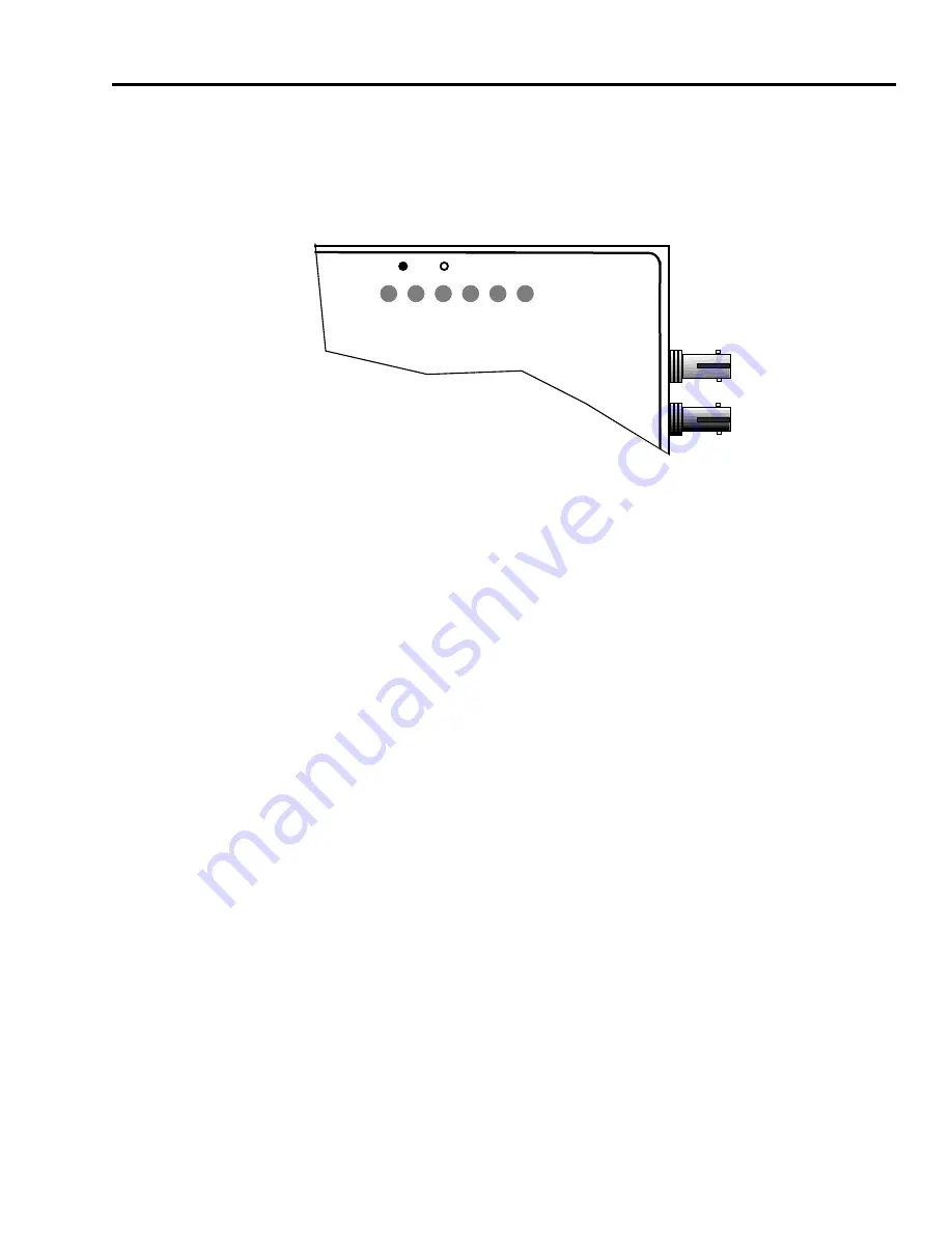
Figure 4-2 shows the location of the LANVIEW LEDs on the 
FOT-F3. This is followed by a description of how to interpret the 
indications of these LANVIEW LEDs.

Figure 4-2 LANVIEW LEDs

Optical Link OK (LNK) LED
When on, this green LED indicates that a link has been 
established between the receive circuitry of the FOT-F3 and the 
transmit circuitry of the fiber optic device at the other end of the 
fiber optic link segment. This LED remains on as long as the link 
is maintained. 

To ensure that a link is maintained, the transceiver generates a 
1 MHz idle signal when it is not transmitting data.

Collision (CLN) LED
This red LED flashes to indicate that the FOT-F3 is detecting a 
collision condition. The frequency of flashes increases as the 
network activity increases since more collisions are likely to 
occur. The flash of the LED is pulse-stretched for easy viewing.

802.3 COMPATIBLE SINGLE MODE
FIBER OPTIC TRANSCEIVER
with LANVIEW

®

FOT-F3

SQE

P
W
R

S
Q
E

X
M
T

R
C
V

C
L
N

L
N
K

TX

RX

1300nm

0461-11

Summary of Contents for EPIM F3

Page 1: ...FOT F3 FIBER OPTIC TRANSCEIVER USER S MANUAL...

Page 2: ......

Page 3: ...CONSEQUENTIAL DAMAGES WHATSOEVER INCLUDING BUT NOT LIMITED TO LOST PROFITS ARISING OUT OF OR RELATED TO THIS MANUAL OR THE INFORMATION CONTAINED IN IT EVEN IF CABLETRON SYSTEMS HAS BEEN ADVISED OF KN...

Page 4: ...h the operator s manual may cause harmful interference to radio communications Operation of this equipment in a residential area is likely to cause interference in which case the user will be required...

Page 5: ...the standards set by the Voluntary Control Council for Interference by Information Technology Equipment VCCI aimed at preventing radio interference in commercial and or industrial areas Consequently w...

Page 6: ...EEC EC Directive 73 23 EEC EN 55022 EN 50082 1 EN 60950 Equipment Type Environment Networking Equipment for use in a Commercial or Light Industrial Environment We the undersigned hereby declare that t...

Page 7: ...2 INSTALLATION REQUIREMENTS 2 1 NETWORK DESIGN GUIDELINES 2 1 2 1 1 Fiber Optic Requirements 2 1 2 1 2 AUI Cable Requirements 2 2 CHAPTER 3 INSTALLATION 3 1 UNPACKING THE FOT F3 3 1 3 2 CONNECTING TH...

Page 8: ...OUT 4 1 4 1 1 Testing the Fiber Optic Link Segment 4 1 4 1 2 Testing the FOT F3 Fiber Optic Transceiver 4 3 4 2 USING LANVIEW 4 4 APPENDIX A SPECIFICATIONS A 1 FIBER OPTIC INTERFACE A 1 A 2 AUI CONNE...

Page 9: ...the FOT F3 and its capabilities This manual is organized as follows Chapter 1 Introduction discusses the capabilities of the FOT F3 outlines the conventions used in this manual provides information o...

Page 10: ...Contains information essential to avoid damage to the equipment 1 3 OVERVIEW OF THE FOT F3 The FOT F3 Fiber Optic Transceiver Fiber Optic Medium Attachment Unit or FOMAU Figure 1 1 is a device that al...

Page 11: ...ed in FOIRL specifications It provides the flexibility to connect to networks using Ethernet Version 1 Version 2 and or IEEE 802 3 equipment through an AUI port However the FOT F3 uses 1300 nm wave le...

Page 12: ...et then a distance of over five kilometers is possible with single mode cable However Cabletron Systems only supports a distance of 5 kilometers If using 62 5 125 multimode cable signal distance is ab...

Page 13: ...3 LANVIEW LEDs The FOT F3 incorporates Cabletron Systems LANVIEW diagnostic and monitoring system LANVIEW is a series of LEDs incorporated into all Cabletron Systems products If a problem arises trou...

Page 14: ...ED flashes to indicate that the FOT F3 is transmitting frames onto the network RCV Receive This yellow LED flashes to indicate that the FOT F3 is receiving frames from the network CLN Collision This r...

Page 15: ...MMAC 5 with a FOMIM 32 36 38 The MMAC serves as an intelligent repeater hub that links the fiber optic link segment to other network segments regardless of media type The link segment is attached to t...

Page 16: ...ters runs from the FOT F3 3 to another FOT F3 5 The hardware connection is completed via another AUI cable 6 to a Cabletron Systems NBR 220 Ethernet Bridge 7 configured to provide an AUI interface Thr...

Page 17: ...t mail support ctron com By FTP ctron com 134 141 197 25 Login anonymous Password your email address Before calling Cabletron Systems Technical Support have the following information ready A descripti...

Page 18: ...al Authorization RMA numbers 1 5 RELATED MANUALS Use the manuals identified below to supplement the procedures and other technical data provided in this manual The procedures contained in these manual...

Page 19: ...ELINES The following design guidelines must be met when connecting devices using the FOT F3 2 1 1 Fiber Optic Requirements The fiber optic link segments should consist of single mode 8 125 12 125 m fi...

Page 20: ...e it takes a packet to travel from the sending device to the receiving device If the total one way propagation delay between any two nodes anywhere in the network exceeds 25 6 s use some form of segme...

Page 21: ...et before installing the transceiver 3 1 UNPACKING THE FOT F3 Before installing the FOT F3 visually inspect the transceiver and check the contents of the accessory package To unpack the transceiver 1...

Page 22: ...to the transceiver before you begin the installation procedures 3 2 1 Setting the SQE Switch The Signal Quality Error SQE Test Switch allows you to enable or disable the SQE heartbeat test function Th...

Page 23: ...2 Connecting the AUI Cable To connect your Ethernet device to the FOT F3 attach an AUI cable as follows See Figure 3 2 1 Attach an AUI cable to the device to which the FOT F3 will be connected OT F3...

Page 24: ...lit indicating the transceiver is receiving power from the device Also if the SQE test is enabled the SQE LED should be lit Figure 3 2 AUI Connection If the PWR LED is not lit perform the following st...

Page 25: ...ber Optic Cable This section describes how to connect the fiber optic link segment to the FOT F3 Perform the following steps only after testing the fiber optic cable to ensure that the cable has no de...

Page 26: ...s If the ends become contaminated clean them with a soft clean lint free cloth and alcohol Connect the fiber optic cable to the FOT F3 as follows 1 Remove the protective plastic covers from the fiber...

Page 27: ...ff perform each of the following steps until the LED is on a Check that the power is on for the device at the other end of the link b Verify that the fiber strands are properly connected to each port...

Page 28: ...ber optic segment to be easily connected to the transceiver Allows the AUI cable to be easily connected from the transceiver to the workstation Has a smooth dirt free surface which accepts the adhesiv...

Page 29: ...ief to cables connected to a surface mounted FOT F3 proceed to Section 3 4 1 For a FOT F3 that is not surface mounted proceed to Section 3 4 2 3 4 1 Cable Strain Relief for Surface Mounted FOT F3 Refe...

Page 30: ...e strain to cables connected to a FOT F3 that is not surface mounted proceed as follows 1 If possible use long tie wraps to secure the FOT F3 to a structural support such as a beam or a rafter 2 Using...

Page 31: ...ON FOT F3 USER S MANUAL 3 11 The FOT F3 is now ready for operation We recommend that you test the system prior to transmitting data Refer to Chapter 4 Testing And Troubleshooting for information about...

Page 32: ...CHAPTER 3 INSTALLATION 3 12 FOT F3 USER S MANUAL...

Page 33: ...r it has been installed to ensure that the physical layer of the network is operating properly 4 1 1 Testing the Fiber Optic Link Segment Test the segment being attached to the FOT F3 to verify that t...

Page 34: ...est level 9 Subtract the reference level found in step 4 from the test level to find your dB loss for the fiber optic link segment i e dB loss Test Level Reference Level 10 Verify that the reading on...

Page 35: ...able of generating valid data packets such as the LAN MD are required for this procedure Refer to Figure 4 1 and proceed as follows 1 Using an AUI cable 2 connect a LAN MD 1 to the FOT F3 3 Figure 4 1...

Page 36: ...test 4 NODE on the LAN MD connected in step 2 Verify that this test passes At least 100 packets should be sent and received with no errors The packets will be received and sent back from the SERVER LA...

Page 37: ...ther end of the fiber optic link segment This LED remains on as long as the link is maintained To ensure that a link is maintained the transceiver generates a 1 MHz idle signal when it is not transmit...

Page 38: ...rk by the device connected to the transceiver The flash of the LED is pulse stretched for easy viewing This LED stays off if the device is active but not transmitting traffic onto the network Signal Q...

Page 39: ...R LED When on this green LED indicates that the transceiver is receiving power from the device connected to the FOT F3 AUI port If this LED is off power is not being received from the device or the DC...

Page 40: ...CHAPTER 4 TESTING AND TROUBLESHOOTING 4 8 FOT F3 USER S MANUAL...

Page 41: ...1 lists the parameters along with the associated typical and minimum maximum specifications Table A 1 Fiber Optic Interface Specifications Parameter Typical Minimum Maximum Transmitter Peak Wave Lengt...

Page 42: ...the typical power output at 25 C is 16 4 dBm For a 4 C temperature increase multiply the typical coefficient 0 07 dB by four and add the result to typical output power 4 C x 0 07 dB C 16 4 dBm 16 7 dB...

Page 43: ...the specifications of the power supply in the FOT F3 Table A 2 Power Supply Specifications Parameter Typical Value Worst Case Current 425 mA 475 mA Input Voltage 9 0 V 7 5 15 75 V Reset Time 500 ms 7...

Page 44: ...nd 73 23 EEC Electromagnetic Compatibility The FOT F3 meets the EMC requirements of FCC Part 15 Class A EN 55022 Class A VCCI Class I EN 50082 1 and 89 336 EEC A 6 PHYSICAL The physical specifications...

Reviews: