


Ethernet Switch Module User Guide
Page 5-1
CHAPTER 5
DIAGNOSTICS AND TROUBLESHOOTING
5.1 POWER-UP DIAGNOSTICS
Built-in diagnostic capabilities for the Ethernet Switch Modules include:
•
Power-up diagnostics, which are run every time an Ethernet Switch
Module is brought online.
•
Front panel status LEDs.
•
Local and remote loopback tests.
•
Temperature sensors.
5.1.1
Power-up Tests
The power-up diagnostics assure that the ATX and all the installed
modules are operational. During diagnostic mode, the status LEDs are
used differently than during normal operation.
When the ATX is powered-up, it automatically senses the installed boards
and reassigns port numbers starting with the PPE as port 1.
During a normal power-up test, the diagnostics test the entire ATX
starting with the PPE and proceeding slot by slot from the top down. The
normal power-up sequence is described in Chapter 2, Connecting to the
Network.
5.1.2
Power-Up Results
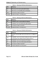
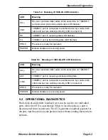
After completion of the power-up diagnostic sequence, all status LEDs on
the ATX front panel should be on (lit), indicating that the modules have
passed the power-up tests. Refer to Tables 5-1 through 5-5. If an Ethernet
Switch Module fails a critical test, it is automatically disabled.
Summary of Contents for 3E02-04
Page 2: ......
Page 30: ...Chapter 4 Monitoring Page 4 4 Ethernet Switch Module User Guide ...
Page 36: ...Chapter 5 Diagnostics and Troubleshooting Page 5 6 Ethernet Switch Module User Guide ...
Page 40: ...Chapter 6 Adding Swapping Modules Page 6 4 Ethernet Switch Module User Guide ...
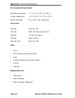
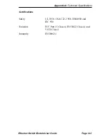
Page 44: ...Appendix A Technical Specifications Page A 4 Ethernet Switch Module User Guide ...
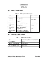
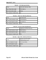
Page 52: ...Appendix B Cables Page B 8 Ethernet Switch Module User Guide ...
Page 54: ...Index Index 2 Ethernet Switch Module User Guide ...


