E-3
cab Produkttechnik GmbH & Co KG
1
8
9
10
8
11
6
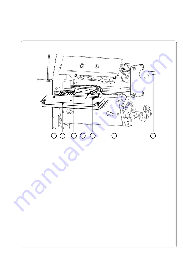
6. Carefully unplug the printhead (
1
) from the connectors of the printhead
cables (
9 and 10
).
7. Connect the new printhead to the cables.
8. Place the printhead into the assembly and insert the holes (
8
) onto the
pins (
11
).
9. Tighten the locking screw (
5
) by hand. Check that the printhead is
completely secured in the printhead carriage.
10. Swing the lever (
6
) again into the position shown in figure E-2.
11. Tighten the locking screw (
5
) completely. Do not over-tighten the locking
screw (
5
).
Fig. E-3 Changing Printhead A3/A4 (II)
Appendix E - Replacing Assembly Units
Summary of Contents for A4
Page 1: ...Edition 4 03 Thermal Transfer Printer Operator s Manual ...
Page 55: ...55 cab Produkttechnik GmbH Co KG This page is intentionally left blank 7 Media Loading ...
Page 77: ...77 cab Produkttechnik GmbH Co KG A B D C E F 9 Test Options Fig 9l Status Print ...
Page 83: ...83 cab Produkttechnik GmbH Co KG 9 Test Options Fig 9o Printhead Profile ...
Page 87: ...87 cab Produkttechnik GmbH Co KG 9 Test Options Fig 9s Test Grid ...
Page 104: ...104 cab Produkttechnik GmbH Co KG This page is intentionally left blank 11 External Keyboard ...


