background image

8

9

3.1 

Structure of the Control Panel
The user can control the operation of the printer with the control panel, for example:
•  Issuing, interrupting, continuing and canceling print jobs,
•  Setting printing parameters, e.g. heat level of the printhead, print speed, interface configuration, language and 

time of day (

 Configuration Manual), 

•  Start the test functions (

 Configuration Manual), 

•  Control stand-alone operation with a memory module (

 Configuration Manual),

•  Update the firmware (

 Configuration Manual).

Many functions and settings can also be controlled by software applications or by direct programming with a 

computer using the printer’s own commands. 

 Programming Manual for details.

Settings made on the control panel make the basic settings of the label printer.

i

Notice! 

It is advantageous, whenever possible, to make adaptations to various print jobs in the software.

1

2

Ready

6

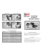
The control panel consists of a graphic display (1) and the navigator pad (2) with five 

integrated keys.
The graphic display indicates the current status of the printer and the print job, 

indicates faults and shows the printer settings in the menu.

Fig. 5 

Control Panel
3.2 

Symbol Displays

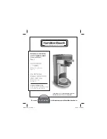
The symbols shown in the following table may appear in the status line of the display, depending on the printer 

configuration. They enable the current printer status to be seen quickly. For the configuration of the status line 

 the 

Configuration Manual.

Symbol Description

Symbol

Description

Symbol Description


Clock


Ethernet link status


User memory in the clock 

circuit


Date sheet


Temperature of the 

printhead


Used memory


Date/time digital


PPP funds


Input buffer


Ribbon supply


Debug window for abc 

programs


Access to memory card


Wi-Fi signal strength


Control of the lower 

display line is handed 

over to an abc 

program


Printer is receiving data

Table 1 

Symbol displays

Control Panel

Summary of Contents for A4+M

Page 1: ...Label Printer Operator s Manual A4 M A4 T ...

Page 2: ... de for the latest update Terms and conditions Deliveries and performances are effected under the General conditions of sale of cab Operator s Manual for the following products Germany cab Produkttechnik GmbH Co KG Postfach 1904 D 76007 Karlsruhe Wilhelm Schickard Str 14 D 76131 Karlsruhe Telefon 49 721 6626 0 Telefax 49 721 6626 249 www cab de info cab de France cab technologies s a r l F 67350 N...

Page 3: ...Inserting a Media Strip into the Printhead 13 4 1 3 Setting the Label Sensor 13 4 2 Loading Fanfold Labels 14 4 3 Loading Transfer Ribbon 15 4 4 Setting the Feed Path of the Transfer Ribbon 16 4 5 Setting the Head Locking System 16 5 Printing Operation 17 5 1 Printhead Protection 17 5 2 Synchronization in Cut Mode 17 5 3 Suppressing Backfeed A4 T only 17 5 4 Avoiding Loss of Material A4 T only 18 ...

Page 4: ...ter is intended exclusively for printing suitable materials that have been approved by the manufac turer Any other use or use going beyond this shall be regarded as improper use The manufacturer supplier shall not be liable for damage resulting from unauthorized use the user shall bear the risk alone Usage for the intended purpose also includes complying with the operating manual including the man...

Page 5: ...ecessary work There are various warning stickers on the device They draw your attention to dangers Warning stickers must therefore not be removed as then you and other people cannot be aware of dangers and may be injured The maximum sound pressure level is less than 70 dB A Danger Danger to life and limb from power supply X X Do not open the device casing 1 4 Environment Obsolete devices contain v...

Page 6: ...mechanics 7 Navigator pad 8 Display Fig 1 Overview 18 16 15 14 13 12 10 9 11 17 9 Ribbon deflection roller 10 Printhead retainer with printhead 11 Guides 12 Allen key 13 Printhead locking lever 14 Print roller 15 Guide roller 16 Label sensor 17 Knob for guide adjustment 18 Tear off plate Fig 2 Print mechanics A4 M 2 Installation ...

Page 7: ...ob for guide adjustment 19 Detent pin 20 Pressing roller system 21 Pinch roller Fig 3 Print mechanics A4 T 22 23 24 25 26 27 28 29 22 Power switch 23 Power connection jack 24 Slot for PC Card Type II 25 Slot for CompactFlash memory card 26 Ethernet 10 100 Base T 27 2 USB master ports for keyboard scanner or service key 28 USB high speed slave port 29 Serial RS 232 C port Fig 4 Connections 2 Instal...

Page 8: ...e 4 2 3 1 Connecting to the Power Supply The printer is equipped with a wide area power unit The device can be operated with a supply voltage of 230 V 50 Hz or 115 V 60 Hz without adjustment 1 Check that the device is switched off 2 Plug the power cable into the power connection socket 20 3 Plug the power cable into a grounded socket 2 3 2 Connecting to a Computer or Computer Network Attention Ina...

Page 9: ...o various print jobs in the software 1 2 Ready 6 The control panel consists of a graphic display 1 and the navigator pad 2 with five integrated keys The graphic display indicates the current status of the printer and the print job indicates faults and shows the printer settings in the menu Fig 5 Control Panel 3 2 Symbol Displays The symbols shown in the following table may appear in the status lin...
Page 10: ...ll to be printed An error has occurred that can be rectified by the operator without interrupting the print job The print job can be continued after the error has been rectified Irrecoverable error and the type of error and the number of labels still to be printed An error has occurred that cannot be rectified without interrupting the print job Critical error and the type of error An error occurs ...

Page 11: ...ate cancel lights Ready Ready Delete internal memory the last label can no longer be reprinted Printing label Printing label Short press g cancels the current print job Longer press g cancels the current print job and deletes all print jobs Pause Pause Correctable error flashes Irrecoverable error 8 lights Error Call Help Concise information for rectifying the fault will be displayed Table 3 Key f...

Page 12: ...o the symbol and thus release the margin stop 4 3 Remove the margin stop 4 from the roll retainer 3 4 Load label roll 2 on the roll retainer 3 in such a way that the labels can be inserted into the printhead in the right position The printing side of the labels must be visible from above 5 Re mount the margin stop 4 onto the roll retainer 3 Push the margin stop 4 until both margin stops 1 4 touch ...

Page 13: ... pressing roller system 15 downwards and lock it with the detent pin 7 Move guides 8 against the edges of the material by turning the knob 11 4 1 3 Setting the Label Sensor The label sensor 9 can be shifted perpendicular to the direction of paper flow for adaptation to the media The sensor unit of the label sensor is visible from the front through the print unit and is marked with an indentation 1...

Page 14: ...assis 1 until it stops Thus the other margin stop 3 will be moved outwards 4 Push label strip between the margin stops 2 3 to print unit via the roll retainer 7 Ensure that the labels on the strip are visible from above 5 Push the outer margin stop 3 until both margin stops 2 3 touch the label strip 6 without clamping or bending it 6 Turn ring 4 clockwise so that the arrow points to the symbol and...

Page 15: ... ribbon supply hub counterclockwise until the transfer ribbon roll is secured i Notice To rewind the transfer ribbon use a core with a width between the width of the supply roll and 115 mm 6 Slide suitable transfer ribbon core 4 onto the transfer ribbon take up hub 5 Position and secure it in the same way as the supply roll 7 Guide transfer ribbon through the print unit as shown in Fig 12 8 Secure...

Page 16: ... ribbon is tightened and the outer edge is tightened in the direction 4 5 Setting the Head Locking System 3 2 1 Fig 14 Setting the head locking system The printhead is pushed on via two plungers 1 In the basic setting the plungers are set in the middle of the printhead retainer This setting can be used for the most applications If the print density decreases in the outer areas when using very larg...

Page 17: ... been loaded 5 2 Synchronization in Cut Mode To guarantee the correct length of the first label a cut prior print job is required X X Activate in the printer driver menu General Print Settings Advanced Setup the setting cut before labels or X X For direct programming use the command C s Programming Manual 5 3 Suppressing Backfeed A4 T only i Notice Feeding back the material to the printhead in the...

Page 18: ...erial can reach a length of more than 300 mm To minimize the loss of material it is necessary to avoid interruptions of the continuos print process X X Interrupt the print process with the pause key only if it is absolute necessary X X Avoid print jobs with a small amount of labels sections especially single prints Optimization of the Data Transfer If sequent labels sections contain differing info...

Page 19: ... may impair the media transport and the print quality X X Lift the printhead X X Remove labels and transfer ribbon from the printer X X Remove deposits with roller cleaner and a soft cloth X X If the roller appears damaged replace it Service Manual 6 3 Cleaning the Printhead Cleaning intervals direct thermal printing every media roll change thermal transfer printing every ribbon roll change Substa...

Page 20: ...rinting is chosen in the software Change to thermal transfer printing Printer prints a sequence of characters instead of the label format Printer is in ASCII dump mode Cancel the ASCII dump mode Printer transports label media but transfer ribbon does not move Transfer ribbon incorrectly inserted Check and if necessary correct the transfer ribbon web and the orientation of the label side Unsuitable...

Page 21: ...f and then on If error recurs call service Head error Hardware error Switch the printer off and then on If error recurs replace printhead Head open Printhead not locked Lock printhead Head too hot Printhead is overheated After pausing the print job will be continued automatically If the fault recurs repeatedly reduce the heat level or the print speed via software Invalid setup Error in the configu...

Page 22: ...rom the computer Press the pause key to skip the command or press the cancel key to cancel the print job Read error Read error when reading from the memory card Check data of the card Backup data reformat card Remove ribbon Transfer ribbon is loaded although the printer is set to direct thermal printing for direct thermal printing remove ribbon for thermal transfer printing set the printer in the ...

Page 23: ... 110 3 5 110 Dl Left margin 0 Dr Right margin 0 E Label thickness 0 025 0 7 F Liner thickness 0 03 0 1 G Thickness label with liner 0 055 0 8 Q Thickness endless material heat shrink tubing pressed heat shrink tubing not pressed 0 055 0 8 0 8 4 5 V Label feed 7 Small label sizes thin materials or strong glue can lead to limitations Critical applications need to be tested and cleared Note the bendi...

Page 24: ... perforation cutter PCU4 with stacker ST4 18 8 19 5 35 3 45 6 46 3 62 1 IT Distance printhead tear off edge 13 5 Print width 105 6 SX Distance gap reflective sensor middle of paper track i e permissible distance of reflex or cut out marks from the middle of the material 53 0 SY Distance gap reflective sensor printhead 46 0 Table 9 Device dimensions ...

Page 25: ... 5 M Height of reflex mark 3 10 X Distance mark material edge 53 0 Z Distance virtual label front edge actual label front edge X X Adjust software settings 0 up to A recomm 0 Reflex marks must be on the back side of the material liner Label sensor for reflex marks on the top side on request Specification is valid for black marks Recognition of colored marks may fail u Preliminary tests are needed ...

Page 26: ...th of cut out mark 5 P Height of cut out mark 2 10 X Distance mark middle of paper track 53 0 Y Sensor recognized virtual label front edge with gap sensor recognition Rear edge cut out Z Distance recognized front edge actual label front edge X X Adjust software settings 0 up to A P Table 11 Cut out mark dimensions Marginal cut out Long hole cut out Rectangular cut out Circular cut out Not recommen...

Page 27: ...010 EN 61558 1 2005 A1 2009 Directive 2004 108 EC relating to electromagnetic compatibility EN 55022 2010 EN 55024 2010 EN 61000 3 2 2006 A1 2009 A2 2009 EN 61000 3 3 2008 Signed for and on behalf of the Manufacturer cab Produkttechnik Sömmerda Gesellschaft für Computer und Automationsbausteine mbH 99610 Sömmerda Sömmerda 27 02 14 Erwin Fascher Managing Director 9 2 FCC NOTE This equipment has bee...

Page 28: ...recoverable error 10 K Key cancel 11 enter 11 feed 11 menu 11 pause 11 Key functions 11 offline menu 11 print mode 11 L Label sensor setting 13 Lithium battery 5 Loading fanfold labels 14 Loading labels 12 Loading labels from roll 12 Loading transfer ribbon 15 Loss of material 18 M Media dimensions 23 N Navigator pad 9 O Offline menu 11 P Pause 10 Power save mode 10 Power supply 4 Printer states 1...

Reviews: