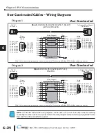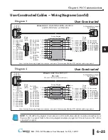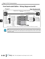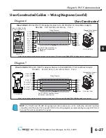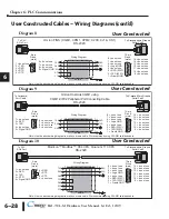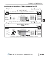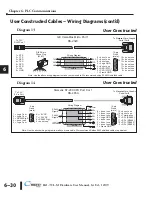
6–33
Chapter 6: PLC Communications
6
EA1-TCL-M Hardware User Manual, 1st Ed., 12/09
®
®
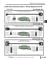
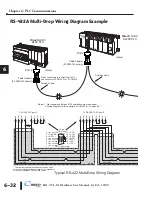
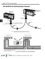
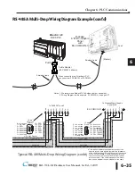
RS-422A Multi-Drop Wiring Diagram Example (cont’d)
Termination resistors required at both ends of the
network receive data signals to match the impedance
of the cable (between 100 and 500 ohms). Jumper pin
13 to 9 on the
C-more
6” Micro-Graphic Serial Port2
15-pin connector to place the 120
⏲
internal resistor
into the network. If the cable impedance is different,
then use an external resistor matched to the cable
Port2
8 = do not use
7 = do not use
6 = do not use
5 = Logic GND
4 = do not use
3 = do not use
2 = do not use
1 = Frame GND
15 = do not use
14 = do not use
13 = Termination
12 = SD– (RS422)
11 = SD+ (RS422)
10 = RD– (RS422)
9 = RD+ (RS422)
1
15
15-pin
D-sub
(male)
Direct
LOGIC
DL06 PLC
Shielded Cable
shield
shield
5
Term.
SHD
SD–
SD+
RD–
RD+
GND
10 9 12 11 13 1
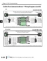
Typical RS-422 Multi-Drop Wiring Diagram (cont’d)
Signal GND
HD = High Density
15-pin
HD D-sub
(male)
8 = do not use
7 = Sig GND
6 = RXD–
5 = do not use
4 = do not use
3 = do not use
2 = do not use
1 = do not use
15 = CTS–
14 = CTS+
13 = RXD+
12 = RTS-
11 = RTS+
10 = TXD–
9 = TXD+
1
6
15
Shielded Cable
Port 2
To
C-more
Micro-Graphic
Serial Port2
TXD+
TXD
RXD
RXD+
Notes: 1. We recommend Belden 8103 shielded cable or equivalent.
2. Wiring Diagram for this example, ZL-CMA15(L), on page 6-27
7
RTS+
CTS–
CTS+
RTS–
RXD–
RXD+
TXD–
TXD+
GND
10 9 6 13 11 14 12 15
Signal GND
To DL06 PLC port 2
TXD+
TXD
RXD
RXD+
(Master)
(Slave)
*
*
RXD
RX
X
SG
+5
V
XD
23
RXD
TXD
ZL CMA15L
X+
RS42 /4 5
RX+
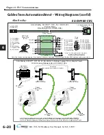
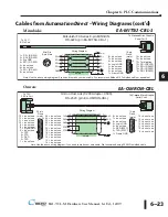
When connecting to a DirectLogic PLC
use connector ZL-CMA15L or ZL-CMA15
C-more
6” Micro-Graphic
Panel
with
EA-COMCON-3
EA COMCON 3
Cable Adapter
(ZL CMA15L shown)

