8–7
Chapter 8: Troubleshooting
8
EA1-MG6-USER-M Hardware User Manual, 1st Ed. Rev C, 09/10
®
No Communications between Panel and PLC
The
C-more
Micro-Graphic panel communicates with a designated PLC or controlling device
through the panel’s RS-232 RJ12 serial communications port (Port1) or RS-232 / RS-485 / RS-
422 communications port (Port2).
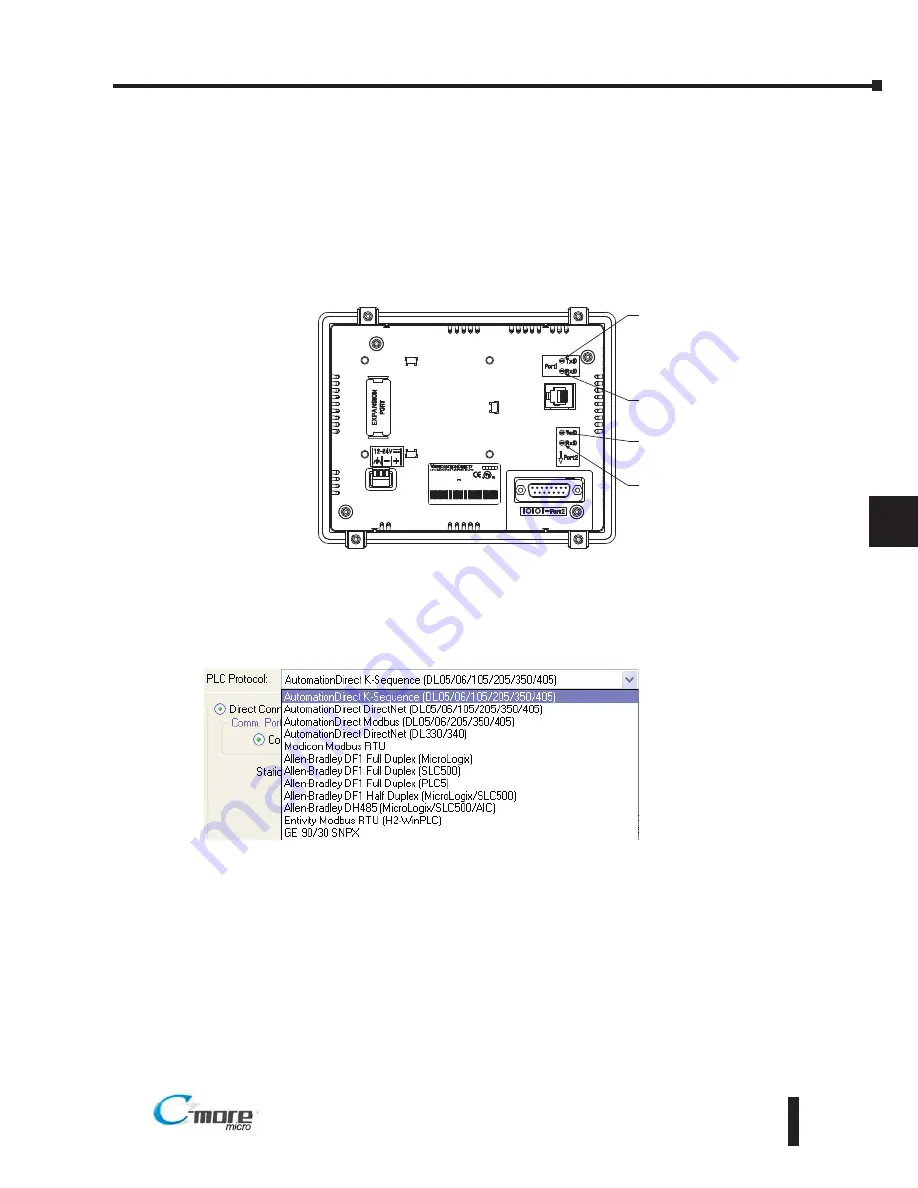
Check the Txd and Rxd status indicators of the port connected to the PLC. The indicator
LED’s should be on or flashing at a fast rate. If there is activity on the LED indicators, then the
panel and PLC are communicating.
On either serial communications port, if there is no activity on one or both TxD and RxD LED
status indicators, then it should be suspected that either:
• The communication settings are incorrect - Open Panel Manager in the C-more Micro-Graphic
programming software and verify that the correct panel Comm. Port is selected. Verify that the
correct PLC protocol is selected and properly configured.
• The cable is bad and needs to be replaced - Try a proven cable.
• Test panel serial port. See Chapter 5, Serial Port - Loop Back Test. If the panel’s serial port is
defective and if a cable is available, switch to the other port on the panel. If possible switch the panel
with a panel that is communicating properly.
• The serial port on the PLC is defective
Electrical noise, pulse generating wiring and/or improper grounding can also cause problems
with communications. Refer to the Electrical Noise Problems section in this chapter for
additional help if electrical noise is suspected. Selecting a lower communication rate in Panel
Manager may help the panel resist noise.
TxD Indicator
Port2
L STED
L STED
7M 7
7M 7
Date code ** *
Date code ** *
4
2
R01.
R01.
MADE N CH NA
MADE N CH NA
EA1-S6MLW + se ial number
EA1-S6MLW + se ial number
MODEL EA1-S6MLW
MODEL EA1-S6MLW
NPUT:12-24V 6.5W
NPUT:12-24V 6.5W
IND CONT.EQ.
IND CONT.EQ.
8
1
15
9
TxD Indicator
Port1
RxD Indicator
Port1
RxD Indicator
Port2


