8
OPERATION
The product to be spread is placed in the hopper. When the spreader is towed forward, the right hand wheel
drives through the pin clutch and gearbox to turn the spinner in a clockwise direction. When the control
handle is pulled forward, the shutter at the bottom of the hopper rotates to an open position. The size of the
opening is set by the adjustable stop pin, which locates into one of five pre-set positions.
An extension of the spinner boss is connected to a stainless steel agitator arm inside the bottom of the
hopper. This agitator ensures that product flows continuously out of the hopper to the spinning disk.
After calibration, fill the hopper to the required level and commence spreading. Do not overfill your hopper;
the maximum permissible payload is 40Kg. To prevent damage to product, disconnect the axle drive pin to
the gearbox until spreading is to be commenced.
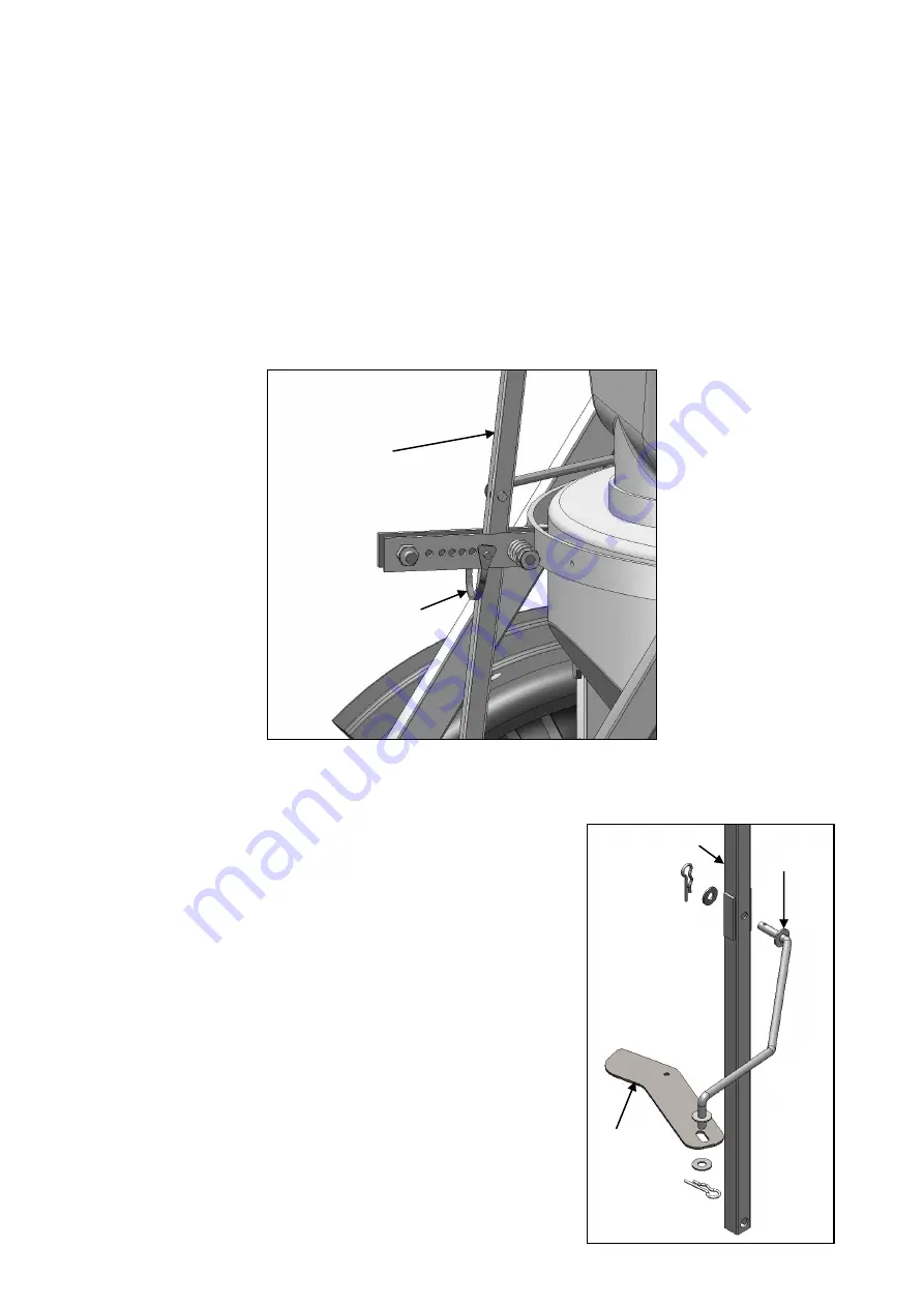
To prevent the shutter from opening during travel to the paddock, move the adjustable stop pin to the rear-
most hole. This will lock the control handle in place and keep the shutter closed. See following diagram.
Adjustable stop pin shown in rear-most hole.
ASSEMBLY
1. Slide the drawbar into the frame and secure using 1 x M12x65 bolt
and Nyloc nut.
2. Slide the Control handle down between the 2 indicator brackets
and fit in place with 1x M10x50 bolt and Nyloc nut, fit 10mm
washer between the arm and the bracket welded to the main
frame.
3. Find the shutter arm. Attach this arm to the control handle and
shutter as shown to the right.
NB: Keep area around the handle and indicator bracket clean and
lubricated after every use.
Adjustable stop pin
Control handle
Control handle
Shutter
Shutter
Arm


