background image

iNetVu New Gen Troubleshooting Guide  

C-COM Satellite Systems Inc. 

Page 32 of 68 


Over Current Protection 

 
Error Code Definition: 
 

0x9003 --- EL Over current  
0x9004 --- AZ Over current  
 

Current used to move the Platform exceeds the fixed limit, which resulted in a current spike. 
 

1. 

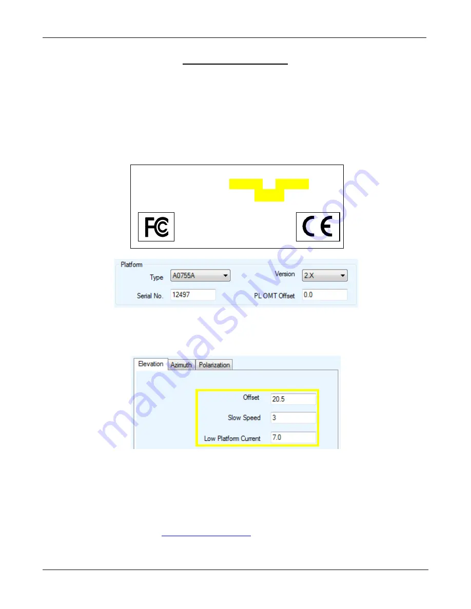
Ensure the correct platform Type is selected with the correct version and serial number.  


2. 

Check the Speeds and Limits for all angles to verify that they are at default. Please see “

Default 

Limits and Configuration Data Tables

” in the 7000 Series Controller User Manual. Reselecting 

the Platform Type will reset these to their default values. 


3. 

If there is any snow/ice buildup or if the unit has been idle in below freezing (-25 to -30 +) 
temperatures for extended periods of time. You may have to move the unit indoors to free up the 
platform. Attempt to move the antenna manually with “HI SPEED ON” from the front panel 
controls. Try to stow and deploying again. 
 

4. 

Increasing the Low Platform Current for that specific angle in increments of 1.0 to test. 
 

5. 

Contact C-COM Support at 

[email protected]

 for further assistance. 


C-COM Satellite Systems Inc. 

Model: iNetVu A0755A   Ver: 2.1 

Serial:  

1250A12497


www.c-comsat.com 

Made In Canada 

Assembled from tested components.  

 Complete system not tested 


Summary of Contents for iNetVu 755

Page 1: ...2015 Revision 3 0 C COM Satellite Systems 5 25 2015 iNetVu New Generation Ka Band Troubleshooting Guide...

Page 2: ...ion is prohibited except as followed under the copyright laws Both the iNetVu and C COM names and logos are registered trademarks of C COM Satellite Systems Inc Intel Pentium is a registered trademark...

Page 3: ...that prevents human exposure to potential radiation hazards For large vehicles with roof mounts the height of the bottom lip of the earth station when fully deployed must be at least six feet above th...

Page 4: ...characteristics of the earth station supplied to them by C COM or C COM s authorized representatives Note 1 This equipment has been tested and found to comply with the limits for a Class B digital de...

Page 5: ...613 745 4110 Fax 1 613 745 7144 General Inquiries info c comsat com Dealer Information dealer c comsat com Support Services support c comsat com Phone 1 613 745 4110 OPT3 Toll Free 1 877 463 8886 OPT...

Page 6: ...ile Platform physically moves but the angle doesn t change 28 OVER CURRENT PROTECTION 31 0X9003 EL OVER CURRENT 32 0X9004 AZ OVER CURRENT 32 SENSOR ERRORS 33 ERROR 0X8911 SENSOR ERRORS 34 SENSOR CABLE...

Page 7: ...0X8915 RF IS TOO LOW OR TRIA IS NOT BEEPING 55 RF Signal Not Being Detected Single IFL Cable Setup 56 RF Signal Not Being Detected Dual IFL Cable Setup 58 MODEM 61 ERROR 0X8801 NO MODEM COMMUNICATION...

Page 8: ...tellite Systems Inc Page 8 of 68 INTRODUCTION About This Manual This manual explains how to troubleshoot common errors on the iNetVu Mobile System 755 and 985 An electronic version of this manual is a...

Page 9: ...0 CONTROLLER SOFTWARE FIRMWARE UPGRADE Quick Tip The software and firmware versions must match for normal operation Minimum Requirements to run IMS Software IMS Version RAM Processor Clock Disk Space...

Page 10: ...the Current Software Note This method describes the steps for upgrading to 7 5 8 1 Ensure the iNetVu software is not running If it is right click the icon on the bottom right of the screen and exit As...

Page 11: ...ersion 7 5 8 Please Note Do not connect the Controller via USB until the drivers and software have been installed 1 If you are installing from the USB flash drive or have downloaded from the C COM FTP...

Page 12: ...FTDI USB Driver and close when completed Click Extract Click Next Click Finish 5 Install the iNetVu 7000 Software and close when completed 6 Connect the Controller using the provided USB cable Window...

Page 13: ...ect No not this time Select Install the software automatically Click Continue Anyway Click Finish 8 You have successfully installed the 7000 iNetVu Drivers and Software Exit the setup wizard 9 You can...

Page 14: ...l see is the new iNetVu Setup Wizard You can choose to continue using the wizard or click NO to proceed to the iNetVu Mobile 7000 software NOTE It is recommended that you continue to the iNetVu Setup...

Page 15: ...iNetVu New Gen Troubleshooting Guide C COM Satellite Systems Inc Page 15 of 68 3 Follow the on screen instructions to update the controller firmware Once complete the wizard will resume...

Page 16: ...iNetVu New Gen Troubleshooting Guide C COM Satellite Systems Inc Page 16 of 68 4 Configure the Platform Type If no changes are needed press Next to continue...

Page 17: ...New Gen Troubleshooting Guide C COM Satellite Systems Inc Page 17 of 68 5 Configure the Service Information Modem If no Modem is to be used please select NA If no changes are needed press Next to con...

Page 18: ...llite Systems Inc Page 18 of 68 6 Configure the Satellite Parameters If no DVB Carrier is to be used you must select RF Search If no changes are needed press Next to continue 7 Once complete Press Yes...

Page 19: ...onfigured launch the software again selecting NO to continue to the iNetVu Mobile 7000 Controls Screen You may also wish to stop this prompt from reappearing Verifying the Upgrade Completed Successful...

Page 20: ...NetVu New Gen Troubleshooting Guide C COM Satellite Systems Inc Page 20 of 68 JAM ERRORS Quick Tip The key to troubleshooting a Jam Error is to determine whether this is a Sensor or Mechanical failure...

Page 21: ...pins 1 and 3 of the controller Using the 7000 controllers front panel select Elevation with HI SPEED on and hold Are you getting 24VDC b If no voltage is shown please turn off the controller and veri...

Page 22: ...assistance d If we are getting voltage on the Motor Cable reconnect the cable and now we will need to test voltage on the internal wiring harness Disconnect the connector going into the Elevation Moto...

Page 23: ...able and the Elevation Tilt Sensor cable If the issue persists continue to the next step b Use the Elevation Tilt Sensor Circuit Diagram on the following page to confirm continuity of the cabling Set...

Page 24: ...iNetVu New Gen Troubleshooting Guide C COM Satellite Systems Inc Page 24 of 68 Sensor Cable and Internal Harness Continuity Test for EL Tilt Sensor Cable...

Page 25: ...iNetVu New Gen Troubleshooting Guide C COM Satellite Systems Inc Page 25 of 68 Internal Harness...

Page 26: ...pins 7 and 9 of the controller Using the 7000 controllers front panel select Azimuth with HI SPEED ON and hold Are you getting 24VDC b If no voltage is shown please turn off the controller and verify...

Page 27: ...her assistance d If we are getting voltage from the Motor Cable reconnect the Motor cable to the Platform Now we will need to test voltage on the wiring harness Disconnect the connector going into the...

Page 28: ...sor Cable and the Azimuth Encoder cable If the issue persists continue to the next step b Use the Azimuth Encoder Sensor Circuit Diagram on the following page to confirm continuity of the cabling Set...

Page 29: ...iNetVu New Gen Troubleshooting Guide C COM Satellite Systems Inc Page 29 of 68 Sensor Cable and Internal Harness Continuity Test for AZ Encoder Sensor Cable...

Page 30: ...iNetVu New Gen Troubleshooting Guide C COM Satellite Systems Inc Page 30 of 68 Internal Harness...

Page 31: ...iNetVu New Gen Troubleshooting Guide C COM Satellite Systems Inc Page 31 of 68 OVER CURRENT PROTECTION...

Page 32: ...ser Manual Reselecting the Platform Type will reset these to their default values 3 If there is any snow ice buildup or if the unit has been idle in below freezing 25 to 30 temperatures for extended p...

Page 33: ...iNetVu New Gen Troubleshooting Guide C COM Satellite Systems Inc Page 33 of 68 SENSOR ERRORS Quick Tip A red indicator on the iNetVu Controls screen indicates a critical failure...

Page 34: ...Sensor Cables appear the same they are NOT interchangeable Azimuth Encoder Elevation Tilt Sensor Wiring Harness 7000 Controller Solution Step 1 a From the Maintenance Screen ensure the correct Platfo...

Page 35: ...continuity the problem could be related to the Sensor itself b If the Sensor Error is related to either Polarization or Elevation you could swap the PL Tilt with the EL Tilt or vise versa to see if th...

Page 36: ...iNetVu New Gen Troubleshooting Guide C COM Satellite Systems Inc Page 36 of 68 Internal Harness for EL Tilt...

Page 37: ...iNetVu New Gen Troubleshooting Guide C COM Satellite Systems Inc Page 37 of 68 Sensor Cable and Internal Harness Continuity Test for AZ Encoder Sensor Cable...

Page 38: ...iNetVu New Gen Troubleshooting Guide C COM Satellite Systems Inc Page 38 of 68 Internal Harness...

Page 39: ...iNetVu New Gen Troubleshooting Guide C COM Satellite Systems Inc Page 39 of 68 COMPASS Quick Tip Compass interference Try overriding the compass and using full search...

Page 40: ...bile Platform 2 Go to Maintenance 3 Click Check Compass 4 The Mobile Platform will now rotate on 90 intervals 0 90 180 270 90 These figures are in relation to true North 5 Pay attention to the Compass...

Page 41: ...ation Do not calibrate unless instructed by C COM Technical Support Restoring the Compass 1 Launch the iNetVu Software and proceed to the Maintenance Compass Tab Click Restore CP 2 Check the Compass o...

Page 42: ...iNetVu New Gen Troubleshooting Guide C COM Satellite Systems Inc Page 42 of 68 GPS Quick Tip GPS failure For emergency deployment try GPS Override and enter the LAT LONG manually...

Page 43: ...he sky Cause 3 Overcharge in the GPS Antenna Cable Solution 3 Turn off the Controller Unplug GPS Antenna from the back of the 7000 Controller and ground it Wait 5 seconds Re connect GPS Antenna and tu...

Page 44: ...Guide C COM Satellite Systems Inc Page 44 of 68 For emergency deployment the GPS can be overridden and the LAT LONG entered manually from the iNetVu 7000 Software or Web Interface iNetVu 7000 Software...

Page 45: ...iNetVu New Gen Troubleshooting Guide C COM Satellite Systems Inc Page 45 of 68 STOW Quick Tip The controller cannot stow the platform if any of the stow limit switches fail to enable...

Page 46: ...006 These switches not getting enabled can be caused by The Controller The Sensor Cable The Internal Wiring Harness The Switch Itself AZ The Switch is too close to the target therefore needs to be adj...

Page 47: ...act with metal indicated by an LED on the switch and the AZ ST from the 7000 Software Controls screen When the switch is moved away from any metal object it should activate Antennas with the switch on...

Page 48: ...u Mobile 7000 Controls screen does the AZ ST come ON If YES this concludes the Switch has failed If NO proceed to Step 3 Step 3 Testing the Sensor Cable a Disconnect the sensor cable from the Platform...

Page 49: ...e paper clip on the connector shorting out the pins corresponding to the Switch you wish to test 6 9 and 6 18 for Azimuth ST b From the iNetVu Mobile 7000 Controls screen does the AZ ST come ON If YES...

Page 50: ...he manual controls on the front of controller move the platform to the stow position on 2 axes Move the AZ 0 0 then begin to lower the antenna until stowed 755 985 stow position b Once the controller...

Page 51: ...oes the Elevation ST come ON If YES it concludes the limit switch is too far from the target and it needs to be brought closer until the Elevation ST comes on Loosen the nut and slowly thread the Sens...

Page 52: ...connect the sensor cable from the Platform and place the paper clip on the sensor cable shorting out pins corresponding to the Switch you wish to test A D for EL ST b From the iNetVu Mobile 7000 Contr...

Page 53: ...aper clip on the connector shorting out pins corresponding to the Switch you wish to test 5 9 and 5 18 for Elevation ST b From the iNetVu Mobile 7000 Controls screen does the Elevation ST come ON If Y...

Page 54: ...iNetVu New Gen Troubleshooting Guide C COM Satellite Systems Inc Page 54 of 68 RF SIGNAL LOSS...

Page 55: ...1 Verify all the physical connections are properly connected by referring to Quick Start Guides Verify the controller is properly configured by referring to the Quick Start Guides The modem must be pr...

Page 56: ...l State This indicates the controller is not configured correctly and you will not be able to deploy the dish resulting in ERROR 0X8915 RF IS TOO LOW Ensure the controller is configured correctly Toow...

Page 57: ...dem or contact your service provider If proper voltage is displayed reconnect the cable and proceed to Step 3 Step 3 Disconnect the coax cable going into the TX cable on the antenna Measure voltage on...

Page 58: ...ow Red Abnormal State As the TRIA is being power by the controller the platform will not be able to deploy and you will receive ERROR 0X8915 RF IS TOO LOW Ensure the controller is configured correctly...

Page 59: ...er source is making it all the way up to the LNB Starting with the Modems port disconnect the coax cable and using a volt meter to determine if the modem is outputting voltage Please check with your I...

Page 60: ...r replace the cable If the voltage does match reconnect the cable and proceed to Step 6 Step 6 Disconnect the RX coax connected to the TRIA Measure voltage on this cable If the voltage does not match...

Page 61: ...iNetVu New Gen Troubleshooting Guide C COM Satellite Systems Inc Page 61 of 68 MODEM...

Page 62: ...itions No Modem Communication Error Code 0x8800 0x88FF Network UART Reset Communication between controller and modem has not been established Modem TX Disabled Communication between controller and mod...

Page 63: ...Verify the controller and modems IP address are correct c Connect the Modem directly to the Controllers Ethernet port bypassing any routers hubs or switches d Swap out the Ethernet Cable Please conta...

Page 64: ...iNetVu New Gen Troubleshooting Guide C COM Satellite Systems Inc Page 64 of 68 CANNOT FIND SATELLITE Quick Tip In most cases when you cannot find satellite it is due to improper configuration...

Page 65: ...le to find satellite Possible Causes Improper Configuration Line of Sight coverage Faulty Hardware Modem has not been provisioned Step 1 There must be no RED YELLOW indicators on the Controls Screen o...

Page 66: ...s provided by your NOC or service provider For Tooway Service this is preconfigured so no changes are necessary Please see the Quick Start Guide for proper configuration For HN Ka Service please see t...

Page 67: ...h search starting point This is also known as the System Ref AZ The antenna will use this value to start searching based on a 120 azimuth search window A System Ref AZ of 30 2 will have a search windo...

Page 68: ...10 medium M12 75 medium 39 medium 20 medium Torque Nm Socket Head ISO 4762 DIN 912 Hex Head ISO 4014 4017 DIN 931 933 Torque Nm Torque Nm Socket Set Screw ISO 4026 4029 DIN 913 916 noted tightening to...

Reviews: