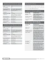
ByoPlanet MS-700 Operator'S Manual Download Page 7

SYSTEM COMPONENTS

The patented MS-700™ Electrostatic Sprayer was engineered 
with the end-user in mind. It is durable, highly mobile and 
incredibly effective for electrostatic delivery.

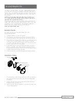
The peristaltic pump is the only field-serviceable component. 
If you are experiencing issues with your device, please con-
tact Customer Support at 

WWW.SERVICETECHTEAM.COM

.

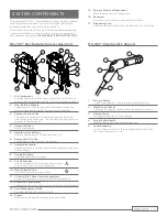
MS-700™ Electrostatic Sprayer Base Unit

1. 

Air Compressor


Atomizes and propels the liquid. Includes built-in auto-re-
setting thermal safeguard against compressor overheating.

2.  Non-Marking Wheels


Large wheels, for easy transport and maneuverability, 
will not leave scuff marks. Do not require inflation.

3.  Sprayer Connect Line


Connect line consists of three components: electrical 
line, liquid line and air line. The connect line connects the 
sprayer to the base unit.

4.  Sprayer Holster


Holds the sprayer.

5.  Handle Adjust Buttons


Adjusts handle height. (Squeeze to adjust.)

6.  Removable Drip Cup


Collects any dripping from the sprayer.

7.  Adjustable Handle


Handle position is raised, lowered and rotated by the two 
button snaps.

8.  Peristaltic Pump


Provides liquid up to sprayer.

9.  Circuit Breaker


User resettable circuit breaker and will only  
trip if a short occurs in the base unit.

10.  Main Power Switch  

Powers system to a ready state.

11.  1-Gallon (3.8 Liters) Product containers


Product Containers (not included with equipment).

12.  Extension Cord Holder  

Located at the rear of the unit for extension cord storage.

13.  Cord Management Hook


Stores or hangs the extension cord.

14.  Frame  

Base casing designed for long-term durability. 
 

15.  Sprayer Electrical Disconnect


Electrical connection for sprayer.

16.  Reservoir  

A reservoir to ensure a consistent liquid flow.

17.  Dispensing Cap  

Allows solution to flow from the bottle to the liquid line.

MS-700™ Electrostatic Sprayer

1. 

Sprayer Button  

1-click functionality / operates the sprayer/device.

2.  Main Control Panel  

Indicates the power, sprayer and electrostatics are on.

3.  Nozzle Cover  

Located on the front of the sprayer.

4.  Spray Wand Handle  

Handle positioned for ambidextrous use.

5.  Loom Assembly  

Connect line consists of three components: electrical 
line, liquid line and air line.

ENGLISH  |  7

BYOPLANET.COM

Summary of Contents for MS-700

Page 1: ...ByoPlanet com OPERATOR S MANUAL For Indoor and Outdoor Commercial Use For service and support contact www ServiceTechTeam com Operator s Manual ENGLISH 2 11...

Page 2: ...TEM COMPONENTS MS 700 Electrostatic Sprayer Base Unit 7 MS 700 Electrostatic Sprayer 7 OPERATING INSTRUCTIONS Preparing the Spray Area 8 Unit Operation Setup 8 Sprayer Operation During Cleaning 8 Chan...

Page 3: ...is manual Stop operation immediately if static sparking occurs or you feel shock Do not use equipment until you identify and correct the problem Use and clean equipment only in well ventilated area Ne...

Page 4: ...e equipment when in the work area to help prevent serious injury Refer to product specific ByoPlanet Safety Data Sheets SDS for any additional Personal Protective Equipment PPE EQUIPMENT MISUSE HAZARD...

Page 5: ...resistance for an electric current to reduce the risk of electric shock This appliance is equipped with a cord having an equip ment grounding conductor and a grounding plug The plug must be plugged in...

Page 6: ...ever hang unit from cord 12 A sprayer should never be left unattended when plugged in 13 A resettable breaker is provided on the rear of the unit It will trip if the unit experiences an electrical sho...

Page 7: ...e Handle Handle position is raised lowered and rotated by the two button snaps 8 Peristaltic Pump Provides liquid up to sprayer 9 Circuit Breaker User resettable circuit breaker and will only trip if...

Page 8: ...w areas moving the sprayer in a sweeping motion until surfaces are thoroughly wet Optimal spray distance away from surface is 2 4 feet 0 6 1 2 meters 15 After spraying keep the area closed to the publ...

Page 9: ...rom the device 2 When not in use ensure the device is powered off and unplug the power cord from the wall outlet and device 3 Wipe exterior surfaces of the device including hose and nozzle with a slig...

Page 10: ...penings and clear dislodge Flip the power switch back to the ON posi tion If the problem persists the user should let the unit sit for 30 minutes to see if it s an overheat ing issue If the unit still...

Page 11: ...chteam com to request replacement parts If unit has been stored without use for extended period of time peristaltic pump may not operate properly upon startup The user should run the unit for 5 minute...

Page 12: ...220 0550 FOR CUSTOMER COLLATERAL INCLUDING OPERATOR S MANUAL AND QUICK START GUIDES SERVICETECHTEAM COM 1 877 220 0550 QUESTIONS SERVICETECHTEAM COM CONTACT US FOR DEVICE WARRANTY INFORMATION SERVICE...

Reviews: