Section 4
– Assembly
SG Section 4- 6 -
2.
Solder the Neck pickup shield (ground) wire to the case of the Neck Volume control;
3.
Repeat steps 1-2 for the Bridge Tone control and Bridge pickup wiring;
4.
Recheck all electrical connection to ensure wiring integrity;
5.
Carefully tighten all controls in place
–
take care of your finish!
6.
Install the control knobs by turning all controls clock wise, then push on the control knobs with
the same orientation of the number scale.
4.2.4
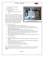
Selector Switch Wiring and Installation (Reference Figure 4.2.4)
The Selector switch allows you to choose either the Bridge pickup, the Neck pickup or both for output to
your amplifier. Note that the switch position shown in Figure 4.2.4 also represents the installed position
of the switch.
1.
Bridge
input:
a.
Trim & tin
shielded wire;
b.
Solder to upper switch terminal
(check Fig. 4.2.4).
2.
Switch
output:
a.
Trim & tin
shielded wire;
b.
Solder to the middle
two
switch terminals (check Fig. 4.2.4).
3.
Ground:
a.
Check the length of the common
shield ground wire
–
solder an
additional length of wire (2
–
3
inches) if necessary;
b.
Solder to switch ground
terminal.
4.
Neck
input:
a.
Trim & tin
shielded wire;
b.
Solder to the lower switch
terminal (check Fig. 4.2.4);
5.
While keeping the orientation of the
switch action vertical to the Body:
a.
Insert the switch into the switch pocket
–
if necessary, gently pull the harness into the
Audio pocket to take up any slack;
b.
Mount the selector switch with supplied washer and nut.
Tip
…
“tinning” a wire: stripping off
approximately ¼” of insulation, then applying solder
to the exposed wire to make soldering the final
connection easier
Figure 4.2.4 SG Selector Switch


