UK
32
Antiscalant must be dosed in relation to the content of salts, lime etc. in the water and shall be adjusted
on starting up the plant. 0,4 ml of concentrated antiscalant per m³ raw water must be dosed, i.e. if you
have a 1 % solution, the pump shall dose 40 ml/m³.
A flow checking device is installed on the outlet of the dosing pump. This indicates if there is flow or not.
Note! If the flow fails, the check device will register this and stop the plant plus trigger the alarm. (Check
the flow check device and restart the RO plant).
For adjustment of this device, carry out the following steps:
1.
Let the dosing pump operate for approx. 15 minutes until it is warm and all air has been dis-
placed from the pump.
2.
Disconnect the dosing monitor cable (to shortly deactivate the dosing monitoring).
3.
Turn the dial to the left (”-”).
4.
Set the desired operating pressure on the pressure line.
5.
Set the desired dosing amount on the running pump (via frequency and stroke length).
6.
Reconnect the dosing monitoring cable.
7.
The ”Flow” on the pump LCD-monitor flashes for every pump stroke.
8.
Slowly turn the dial of the dosing monitor to the right (”+”), until ”Flow” stops flashing.
9.
Turn the dial back a little once more until ”Flow” starts flashing again.
Now turn the stroke length of the pump back approx. 20 % (scale parts) (note the old value) –
”Flow” should stop flashing. If not you must turn again the dial of the dosing monitor slowly to
the right (”+”), until ”Flow” stops flashing. Note: ”flow” vanishes from the display when the Reed
switch has been switched off (when the float is in top position).
10.
Reset the stroke length to the old value – ”Flow” should start flashing again.
11.
Check that the dosing nipple (dosing location) is tight, and then the plant is ready for operation.
Important! The stroke length of the dosing pump must not be set at a value below 50 %.
Every week the reservoir must be emptied and rinsed and new antiscalant filled in.
Every third month the reservoir mus tbe rinsed and cleaned before filling in new antiscalant.
Above-mentioned dosing amounts are calculated on basis of our standard dimensioning conditions; if
you are in doubt, BWT will be pleased to calculate the correct amounts for your plant.
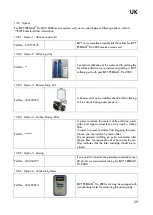
Option 16 – Frequency control of HP-pump
13.8.16
Part No.: 421072005
for Pro 2030-2080
Frequency-controlled high-pressure pump will be
suitable when a specific permeate flow is re-
quired.
Option 17 – Concentrate flow meter
13.8.17
Part No.: 451405100
for Pro 2030-2080
To give a more vaied picture of the capacity of
the RO unit, you may install an optional concen-
trate flow meter.
Summary of Contents for PERMAQ PRO 2000
Page 2: ...UK 2...
Page 11: ...UK 11 Alarm Transport pump 9 2 4 Indication Level low 9 2 5...
Page 19: ...UK 19 13 1 P I Diagram...
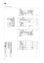
Page 20: ...UK 20 13 2 Layout Drawings...
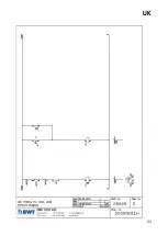
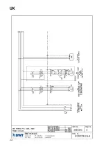
Page 21: ...UK 21 13 3 Wiring Diagram...
Page 22: ...UK 22...
Page 23: ...UK 23...
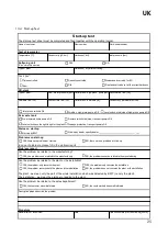
Page 24: ...UK 24...
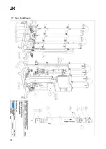
Page 28: ...UK 28 13 7 Spare Parts Drawing...

