UK
31
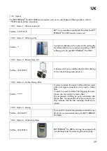
Option 12 – Preparation for CIP
13.8.12
Part No.: 451202016
for Pro 2010-2040
Part No.: 451202007
for Pro 2060-2080
Preparation for CIP consists of connections which ena-
ble installation of a CIP unit on the RO plant
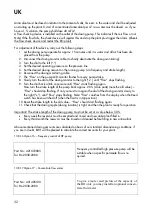
Option 13 – Stationary CIP
13.8.13
Part No.: 421072000
for Pro 2010-2040
Part No.: 421072280
for Pro 2060-2080
During normal operation, depending on inlet, water
quality, temperature, operating conditions etc, the RO
membranes will successively loose capacity due to the
varying content of mineral salts, biological matter,
colloid particles and other insoluble organic particles in
the water. These deposits accumulate during operation
and cause an increased pressure drop across the
membrane and consequently a reduced capacity and
poorer water quality.
In order to prolong the lifetime of the membranes, we
recommend cleaning the membranes with a CIP unit.
Option 14 – Quality flush
13.8.14
Part No.: 451405112
for Pro 2010-2040
Part No.: 451405114
for Pro 2060-2080
The quality flush system monitors that the RO plant
produces permeate <20µS. If the limit value is exceed-
ed, the poor permeate will be led to drain until the
permeate quality has been re-established.
Option 15 – Antiscalant unit
13.8.15
Part No.: 421072270
for Pro 2030-2080
Antiscalant is a product which will be added to the raw
water to avoid precipitation of lime on the membrane,
as these would otherwise clog the membrane.
Application of the antiscalant dosing unit: A water analysis must always be available before starting
up the unit, so that the antiscalant dosing can be adjusted correctly.
Antiscalant is mixed in the measuring reservoir to a 1 % solution. Do not fill in more antiscalant in the
reservoir than for one month’s consumption as the fluid will decay with time and then cannot be used.
Note! If the level switch registers that the minimum level in the antiscalant reservoir has been reached,
an alarm will be triggered and the RO plant stops. (The antiscalant reservoir must be refilled with
cleaning fluid)
Summary of Contents for PERMAQ PRO 2000
Page 2: ...UK 2...
Page 11: ...UK 11 Alarm Transport pump 9 2 4 Indication Level low 9 2 5...
Page 19: ...UK 19 13 1 P I Diagram...
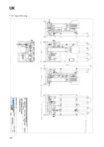
Page 20: ...UK 20 13 2 Layout Drawings...
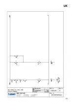
Page 21: ...UK 21 13 3 Wiring Diagram...
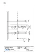
Page 22: ...UK 22...
Page 23: ...UK 23...
Page 24: ...UK 24...
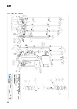
Page 28: ...UK 28 13 7 Spare Parts Drawing...

