background image


43 

   2010 ST-6010 & ST-7210 

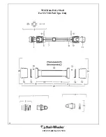
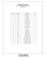
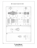
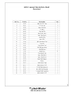
4891 Constant Velocity Drive Shaft 

Parts List 

Ref. No. 

Part No. 

Description 

Qty 

4892 

Slide Collar CV Yoke 

4893 

CV Cross Kit 

4896 

Outer Tube Yoke 

4 4897 

CV 

Body 

4898 

Outer Roll Pin 

5052 

Outer Tube ( Steel ) 

4895 

Inner Tube (Steel) 

4899 

Inner Roll Pin 

9 3945 

Inner 

Yoke 

10 

3946 

Quick Disconnect Yoke 

11 3957 

Cross 

Kit 

12 

5055 

Outer Shield Cone 

13 4904 

Shield 

Support 

Outer 

14 4905 

Shield 

Support 

15 3928 

Shield 

Screw 

12 

16 4906 

Outer 

Shield 

Tube 

17 4907 

Inner 

Shield 

Tube 

18 

4908 

Inner Shield Cone 

19 

3932 

Inner Shield Support 

20 4938 

Washer 

21 

5061 

Shield Safety Chain 

22 

4911 

Ball Collar Kit 1-3/4” 

23 

4912 

CV Half Shaft Complete 

24 

5065 

Inner Half Shaft Complete 

25 

4914 

Complete Shield Assembly 

26 

5070 

Ball Collar Kit 1-3/8” 

Summary of Contents for ST-6010

Page 1: ...540 RPM ST 6010 AND ST 7210 MOWERS OPERATIOR S MANUAL AND PARTS BOOK 5 AND 6 FOOT ROTARY CUTTERS ...

Page 2: ...and these instructions before operating or maintaining the machine Failure to do so could result in personal injury or even death to you or passersby Consult your Bush Whacker dealership if you do not understand the instructions in this manual or need additional information Hall Manufacturing Inc reserves the right to make changes at any time without notice or obligation Additional copies of the m...

Page 3: ...6 7 Attaching Detaching Cutter 8 Rollover 8 9 Rotating Blades 9 Hydraulics 10 Maintenance 11 15 General Maintenance 11 At Least Twice Daily 11 12 Daily 12 13 Every 1 000 Hours or Annually 13 Gearbox Disassembly and Assembly 14 15 Parts book 17 54 Lift Type 18 33 Pull Type 34 53 Miscellaneous 53 54 Warranty Information 55 56 Warranty Registration Card 57 ...

Page 4: ...EATH TO THE OPERATOR BYSTANDERS PASSERSBY OR ANIMALS IN THE AREA General Safety Instructions and Warnings Safety Decals Information Always keep the area around safety decals clean and free of debris so that they can be easily seen and read When installing new components to the equipment it is necessary to obtain new safety de cals from your Bush Whacker dealer and adhere them promptly and properly...

Page 5: ...5 2010 ST 6010 ST 7210 Decals Part Numbers and Placement 4415 4168 4416 2569 4169 FOR 540 RPM 4170 FOR 1000 RPM 2572 ...

Page 6: ...m underneath the mower at very high speeds resulting in property damage injury or even death Always inspect the mowing area prior to the operation of any rotary mower If any of these objects or similar objects are found remove them immediately before operation NEVER operate the mower without the driveline safety shields in place and in proper working order Operation without safety shields can lead...

Page 7: ...and securely supported in the raised position Inadequate support can result in the mower falling which could result in seri ous injury or death Use proper signage around working area This will help the operator have a safe place to work and help passers by to take appropriate precautions Use the proper reflective devices on the equipment to help prevent accidents Make sure that all rules of the ro...

Page 8: ...n and all moving parts both tractor and mower have completely stopped The rotating parts of the tractor and rotary may mower continue to rotate after the PTO has been disengaged THE OPERATOR SHOULD REMAIN SEATED UNTIL ALL MOVEMENT HAS CEASED Never use equipment around railroad tracks without direct railway supervision Inexperience in railway operations may cause loss of communications loss of sign...

Page 9: ...o the blades until all motion has stopped and ma chine is turned off Never operate equipment with loose blades Retighten after the first 8 hours of use and after blade replacement Never allow rotating blades to contact solid objects like rocks posts curbs or guard rails Only operate if all guards and deflectors are in place and in good working condition Rotating Blades Never operate with mower dec...

Page 10: ... needed Stop all leaks Repair or replace hoses as indicated to prevent unexpected failure and possible serious injury to operator or bystander Boiling oil may spray onto hot tractor parts and catch fire causing severe burn injury or death Safety Conclusion Now that the operator has read the information provided in this manual he or she should now be aware of how dangerous a rotary mower can be if ...

Page 11: ...hem Failure to do so could result in serious injury or possibly even death Use marfac double ought grease or cotton picker spindle grease to lubricate all Bush Whacker gearboxes Replacement gearbox grease is available from your Bush Whacker dealership Always use genuine Bush Whacker replacement parts available through the network of authorized dealers The use of non OEM parts will void the warrant...

Page 12: ...requently than normal at least four times a day Always use genuine Bush Whacker replacement blades bolts and nuts Other blades may not meet Hall Manufacturing specifications and could lead to serious injury or death Hydraulics If at any time the hoses become frayed worn or pinched replace them Daily Shields Make sure ALL shields are in place and tightened before operating the mower If one works lo...

Page 13: ...or damage replace if required Frame Look for any structural cracks damage and wear Keep the equipment clean Inspect for debris caught in the machine especially at all pinch points Wheel Hubs Grease wheel hubs at zerk fitting once a day before operating the mower Check seals for leakage Replace seals if a leak is detected Also check bearings for damage If they have seized they are damaged replace t...

Page 14: ... the offset adapter with the mower disengaged from the tractor and firmly on the ground This will prevent the machine from becoming unstable and falling onto the operator Failure to do so might cause serious injury or death to the operator 1 Attach Part D leaving the fasteners slightly loose Note Part D also includes the top link clevis 2 Loosen Part A and slide Part A D to the desired offset Posi...

Page 15: ...15 2010 ST 6010 ST 7210 Partsbook ...

Page 16: ...iption Page Number 1 Front Chain Guard 28 2 Hitch Frame Assembly 17 3 Gear Box Shields 27 4 Gearbox 18 19 5 Access Cover 52 6 Tail A Frame 25 7 Tail Wheel Fork Wheel Assembly 26 8 Rear Chain Guard 28 6010 7210 Lift Type Assembly Breakdown ...

Page 17: ...73 Bolt 2 4 3374 Nut 2 5 3284 Bolt 1 6 3285 Washer 1 7 2077 Nut 1 8 3287 Category I Clevis 1 9 5405 ST 6010 Left Brace 1 9 5388 ST 7210 Left Brace 1 10 5404 ST 6010 Right Brace 1 10 5387 ST 7210 Right Brace 1 11 3148 Nut 4 12 2335 Washer 4 13 2335 Bolt 4 4860 Category II Clevis 1 Hitch Frame Assembly ...

Page 18: ...18 2010 ST 6010 ST 7210 5168 Gear Box See Maintenance Section for Recommended Lubrication ...

Page 19: ... 1 14 5223 GASKET 1 AR 15 5224 GASKET 1 AR 16 5225 GASKET AR 17 5226 SHIM AR 18 5227 SHIM AR 19 5228 SHIM 1 AR 20 5229 SHIM 1 AR 21 5230 SHIM 1 AR 22 5231 SHIM 1 AR 23 5232 SHIM 1 AR 24 5233 SHIM 1 AR 25 5234 SHIM 1 AR 26 5235 SHIM 1 AR 27 5236 SPACER 1 28 5237 COTTER PIN 1 29 5238 COTTER PIN 1 30 5239 BOLT 8 31 5240 BOLT 4 32 5241 NUT 1 33 5242 NUT 1 34 5243 LOCK WASHER 8 35 5244 LOCK WASHER 4 36...

Page 20: ...20 2010 ST 6010 ST 7210 4028 Complete Drive Shaft for ST 6010 Lift Type ...

Page 21: ...28 Shield Screw 6 15 4021 Outer Shield Tube 1 16 4022 Inner Shield Tube 1 17 4012 Shield Safety Chain 2 18 3932 Inner Shield Ring 1 19 4023 Outer Shield Complete 1 20 4024 Inner Shield Complete 1 21 4025 Complete Shield Assembly 1 22 4026 Outer Half Shaft Complete 1 23 4027 Inner Half Shaft Complete 1 24 3925 QD Pin Kit 1 25 4098 Bolt with Nut 8 26 4018 Flange Yoke 1 27 3962 Bushing 1 28 3963 Clut...

Page 22: ...22 2010 ST 6010 ST 7210 4038 Complete Drive Shaft for ST 7210 Lift Type ...

Page 23: ...5096 Complete Clutch Assembly 1 12 3927 Outer Shield Ring 1 13 5085 Shield Bell 2 14 3928 Shield Screw 6 15 5086 Outer Shield Tube 1 16 5087 Inner Shield Tube 1 17 5088 Shield Safety Chain 2 18 3932 Inner Shield Ring 1 21 5089 Complete Shield Assembly 1 22 5091 Outer Half Shaft Complete 1 23 5092 Inner Half Shaft Complete 1 24 3940 Slide Collar Kit 1 25 4098 Bolt with Nut 8 26 4018 Flange Yoke 1 2...

Page 24: ...0 1 1 5425 Blade Bar Only for ST 7210 1 1A 5429 Blade Bar with Stump Jumper for ST 6010 1 1A 5392 Blade Bar with Stump Jumper for ST 7210 1 2 3172 Blade for ST 6010 ST 7210 2 3 3095 Bolt 2 4 2106 Washer 2 5 2105 Nut 2 6 5242 Output Shaft Nut 1 7 5237 Cotter Pin 1 8 3096 Washer 2 Only needed when using Stump Jumper ...

Page 25: ...0 ST 7210 Tail Wheel A Frame Assembly Ref No Part No Description Qty 1 4384 Tail A Frame 1 2 3297 Bolt 2 3 2337 Washer 2 4 2336 Nut 2 5 4458 Bolt 1 6 4378 Bolt 1 7 3148 Nut 2 8 3677 Adjusting Strap 1 9 3718 Washer 2 ...

Page 26: ...el Only 2 piece 1 4 3180 Tire and Wheel less Hub 1 5 3181 Bolt 5 6 3182 Nut 5 7 3183 Bolt 5 8 3184 Nut 5 9 3185 Spacer 1 10 3186 Seal 2 11 3187 Bearing Cone 2 12 3188 Bearing Cup 2 13 3189 Hub with Races and Studs 1 14 3190 Hub Complete with Bearings and Seals REF 15 3191 Spacer 1 16 3192 Axle Bolt 1 10 11 12 4884 Bearing kit 1 18 2513 Nut 1 17 3230 Washer 2 19 4159 Bolt 1 ...

Page 27: ...0 ST 6010 ST 7210 Gearbox Shield and Manual Holder Ref No Part No Description Qty 1 4463 Manual Holder 1 2 4432 Self Tapping Screw 2 3 5173 Gearbox Shield 1 4 5255 Washer 4 5 5244 Lock Washer 4 6 2693 Bolt 4 ...

Page 28: ...GUARD PLATE 2 ROD 3 3583 CHAIN SINGLE ROW Not Shown 3588 CHAIN DOUBLE ROW 4 3585 CLAMP 5 2335 BOLT 6 2337 WASHER 7 2336 NUT ASSEMBLY PART NUMBERS QUANTITIES Ref PN PLATE ROD CHAIN CLAMP BOLT WASHER NUT A 5426 5391 5396 59 1 6 6 6 B 5427 5389 5397 9 1 2 2 2 C 5428 5390 5398 29 1 3 3 3 ...

Page 29: ...29 2010 ST 6010 ST 7210 Skid Shoe Assembly Ref No Part No Description Qty 1 5386 Skid Shoe 2 2 2335 Bolt 4 3 2337 Washer 8 4 2336 Nut 4 ...

Page 30: ...30 2010 ST 6010 ST 7210 ...

Page 31: ...31 2010 ST 6010 ST 7210 Optional Equipment and Other Items not Illustrated ...

Page 32: ...illow Block Bearing Assembly 50 4 Jack Shaft ST 7210 Only 40 5 Gearbox Shield Assembly 27 6 Gear Box 18 19 7 Cylinder 46 8 Center Pivot Assembly 48 9 Axle Arm Assembly 44 10 Tire Wheels 52 11 Rear Chain Guard 28 12 Level Rod 47 13 Access Cover 52 14 Skid Shoe 29 ST 6010 ST 7210 Pull Type Assembly Breakdown ...

Page 33: ...33 2010 ST 6010 ST 7210 Ref No Part No Description Qty 1 4388 Tongue Only 1 2 3374 Nut 2 3 3373 Bolt 2 4 2968 Bolt 1 5 2969 Jack 1 6 3381 Clevis 1 7 2638 Nut 1 Tongue with Fixed Clevis ...

Page 34: ...sembly with Swivel Clevis Ref No Part No Description Qty 1 4408 Swivel Tongue Only 1 2 3374 Nut 2 3 3373 Bolt 2 4 2077 Nut 1 5 3285 Washer 1 6 2969 Jack 1 7 2624 Bolt 1 8 3381 Clevis 1 9 2638 Nut 1 10 3873 Swivel Only 1 11 2076 Bolt 1 ...

Page 35: ...35 2010 ST 6010 ST 7210 Ref No Part No Description Qty 1 4407 Bulldog Tongue Assembly 1 2 3374 Nut 2 3 3373 Bolt 2 4 2969 Jack 1 Tongue Assembly with Bulldog Hitch ...

Page 36: ...36 2010 ST 6010 ST 7210 4005 Complete Drive Shaft For ST 6010 Pull Type Only ...

Page 37: ...4 3928 Shield Screw 6 15 4011 Outer Shield Tube 1 16 4095 Inner Shield Tube 1 17 4012 Shield Safety Chain 2 18 3932 Inner Shield Ring 2 19 4013 Outer Shield Complete 1 20 4014 Inner Shield Complete 1 21 4015 Complete Shield Assembly 1 22 4016 Outer Half Shaft Complete 1 23 4017 Inner Half Shaft Complete 1 24 3925 QD Pin 1 25 4098 Bolt w Nut 8 26 4018 Flange Yoke 1 27 3962 Bushing 1 28 3963 Clutch ...

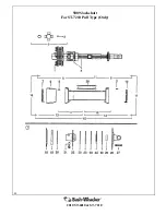
Page 38: ...38 2010 ST 6010 ST 7210 3938 Main Drive Shaft For ST 7210 Pull Type Only ...

Page 39: ...r Tube Yoke 1 11 3946 Quick Disconnect Yoke 1 12 3925 QD Pin 1 13 3947 Shield Bell 2 14 3927 Outer Shield Ring 1 15 3928 Shield Screw 6 16 3948 Outer Shield Tube 1 17 3949 Inner Shield Tube 1 18 3950 Shield Safety Chain 2 19 3932 Inner Shield Ring 1 20 3951 Outer Half Shield Complete 1 21 3952 Inner Half Shield Complete 1 22 3953 Complete Shield Assembly 1 23 3954 Outer Half Shaft Complete 1 24 39...

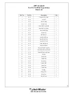
Page 40: ...40 2010 ST 6010 ST 7210 5009 Jackshaft For ST 7210 Pull Type Only ...

Page 41: ...11 4103 Outer Shield Tube 1 12 4109 Inner Shield Tube 1 13 4110 Outer Half Shield 1 14 4111 Inner Half Shield 1 15 4112 Complete Shield Assembly 1 16 4113 Clutch Half Shaft with Shield 1 17 4114 Stub Half Shaft with Shield 1 18 3969 Spring 1 19 3968 Outer Plate 1 20 3963 Clutch Disk 4 21 3967 Bolt w Nut 1 22 3966 Splined Hub 1 23 3965 Inner Plate 1 24 3964 Clutch Plate 1 25 3962 Bushing 1 26 4018 ...

Page 42: ...42 2010 ST 6010 ST 7210 4891 Constant Velocity Drive Shaft ...

Page 43: ... Inner Yoke 1 10 3946 Quick Disconnect Yoke 1 11 3957 Cross Kit 1 12 5055 Outer Shield Cone 1 13 4904 Shield Support Outer 1 14 4905 Shield Support 1 15 3928 Shield Screw 12 16 4906 Outer Shield Tube 1 17 4907 Inner Shield Tube 1 18 4908 Inner Shield Cone 1 19 3932 Inner Shield Support 1 20 4938 Washer 6 21 5061 Shield Safety Chain 2 22 4911 Ball Collar Kit 1 3 4 1 23 4912 CV Half Shaft Complete 1...

Page 44: ...44 2010 ST 6010 ST 7210 Axle Arm Assembly Ref No Part No Description Qty 1 3563 Axle Arm Left Same as Right 1 2 2335 Bolt 4 3 2336 Nut 4 4 3564 Spindle 1 ...

Page 45: ...te Hub Assembly REF Includes Items 2 5 9 10 1 2449 Hub with Cups and Studs only 1 2 2450 Inner Race 1 3 2451 Inner Bearing 1 4 2452 Outer Race 1 5 2453 Outer Bearing 1 6 3359 Spindle Washer 1 7 3372 Spindle Nut 1 8 2456 Dust Cap 1 9 2457 Seal 1 10 2458 Stud Bolt with Nut 5 11 3360 Cotter Pin 1 ...

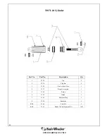
Page 46: ... Ref No Part No Description Qty 1 2330 Pin 2 2 3270 Clip Pin 4 3 3152 Rod w Lock Nut 1 4 3157 Barrel Assembly 1 5 3158 Piston 1 6 3159 Gland 1 7 3165 Breather Plug 1 8 3330 Restrictor 1 REF 3166 Seal Kit 1 REF 3167 Stroke Control Segment Kit AR ...

Page 47: ...ete Assembly for ST 7210 5432 Complete Assembly for ST 6010 Ref No Part No Description Qty 1 5406 Front Level Rod for ST 6010 1 2 2322 Nut 1 3 2321 Turnbuckle 1 4 3066 Rear Level Rod 1 5 2315 Pin 2 6 2313 Cotter Pin 4 1 5394 Front Level Rod for ST 7210 1 ...

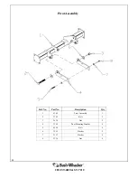
Page 48: ...10 ST 6010 ST 7210 Pivot Assembly Ref No Part No Description Qty 1 4389 Pivot Assembly 1 2 3389 Bolt 2 3 2638 Nut 2 4 3399 Pivot Mounting Bracket 4 5 4550 Bolt 4 6 3259 Washer 2 7 2337 Washer 4 8 2336 Nut 4 ...

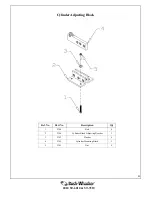
Page 49: ...49 2010 ST 6010 ST 7210 Cylinder Adjusting Block Ref No Part No Description Qty 1 2340 Bolt 4 2 3396 Cylinder Block Adjusting Bracket 2 3 2342 Washer 4 4 5395 Cylinder Mounting Block 1 5 2341 Nut 4 ...

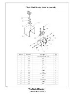
Page 50: ... Bearing Stand 1 2 2335 Bolt 4 3 2336 Nut 4 4 5125 Bolt 4 5 3415 Washer 4 6 2513 Nut 4 7 3659 Bolt 2 8 2337 Washer 4 9 2336 Nut 2 10 3565 Pillow Block 1 11 3392 Shield 1 12 2513 Nut 2 13 3394 Hose Holder 1 14 3393 Washer 2 15 2512 Bolt 2 Pillow Block Bearing Mounting Assembly ...

Page 51: ...justable Three Point Mount 1 10 2337 Washer 12 11 2772 Bolt 12 12 3287 Category I Clevis 1 4860 Category II Clevis 1 13 4380 Left Brace for 6010 13 4381 Left Brace for 7210 1 14 3148 Nut 4 15 3297 Bolt 4 16 3718 Washer 4 17 4383 Right Brace for 7210 1 18 3284 Bolt 1 19 C222 Hitch Pin 2 20 5045 Offset Adapter Subassembly made of items 1 2 3 4 5 6 7 8 9 10 11 12 12A 18 19 At request as separate asse...

Page 52: ...e REF 2489 Rim for 2490 Tire REF 2490 26 Aircraft Type Tire Assembly REF 2622 Foam Filled Tire Implement REF 3275 26 Aircraft Tire Only REF 3276 Tube for 26 Aircraft Tire REF 3516 Foam Filled Aircraft Tire Assembly REF 3083 Access Cover 1 Items not Illustrated For Pull Type Only ...

Page 53: ...l or if the equipment shall have been operated subsequent to its involvement in an accident or breakdown unless the Owner furnishes reasonable evidence that such repair alteration modification or operation subsequent to its involvement in an accident or breakdown was not a cause of the defect The Owner does not return at Owner expense the defective accessory equipment component or machine to or no...

Page 54: ...RRANTY CLAIMS PROCEDURE Warranty claims must be delivered to Hall Manufacturing within thirty 30 days after the warranty service work was performed Hall Manufacturing will approved or deny claim within thirty 30 days of receiving a claim Hall Manufacturing will issue credit for all genuine Bush Whacker parts or components as well as all approved Dealership employee labor time at a rate of 30 00 pe...

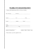
Page 55: ...urchaser _____________________________ Address __________________ City_____________________ State ________ Product ___________________ Model ___________ Serial _____________ Dealer Address City State Signature of Original Buyer Signature of Dealer or Dealer s Agent Please include a copy of the original bill of sale ...

Page 56: ......

Page 57: ...57 2010 ST 6010 ST 7210 Notes ...

Page 58: ......

Reviews: