


PROFIBUS DP data protocol
PROFIBUS manual
Version FELD-V2002.02
Page 17
5.3 Meaning of the contents of the different protocol modes
PLC-Out:
The data refers to the PLC output of the DIGIFORCE
®
. The data described
here is the data transferred from the DIGIFORCE
®
type 9310 to the master.
The function of the PLC-In / PLC-Out bits is identical to the parallel PLC I/O
ports on the unit itself and can be found from the operating manual for the
unit.
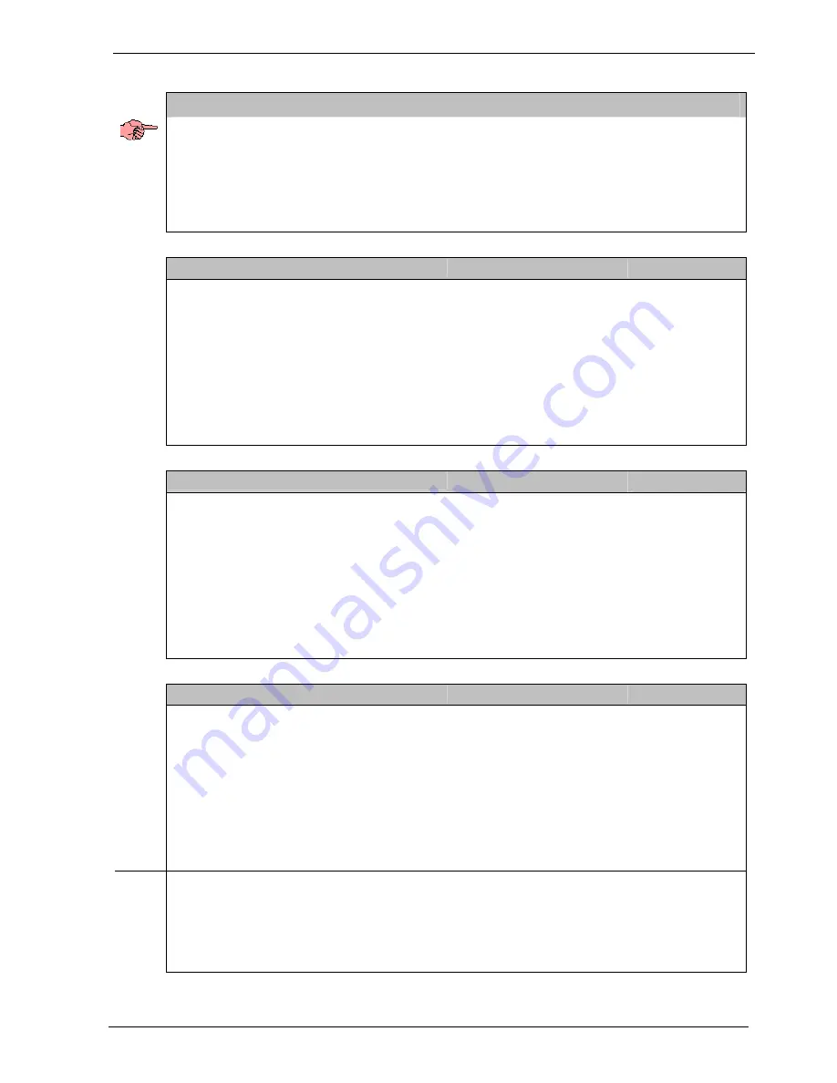
5.3.1 PLC outputs Byte 1 (PLC signal lines OK/NOK, Ready etc.)
PLC outputs Byte 1 (Slave
Æ
Master)
Valid values:
S2
Bit 0 LSB
S1 Bit
1
Spare bits to are set to '0'
NOK online
Bit 2
NOK Bit
3
OK Bit
4
READY Bit
5
spare Bit
6
spare
Bit 7 MSB
5.3.2 PLC outputs Byte 2 (program addressing, switching points)
PLC outputs Byte 2 (Slave
Æ
Master)
Valid values:
STROBE
Bit 0 LSB
Prog0 Bit
1
Spare bits to are set to '0'
Prog1
Bit 2
Prog2 Bit
3
OK-STEST Bit
4
Test running
Bit 5
spare Bit
6
spare
Bit 7 MSB
5.3.3 PLC outputs Byte 3 (device status)
PLC outputs Byte 3 (Slave
Æ
Master)
Valid values:
Status 2
0
Bit 0 LSB
Status 2
1
Bit
1
Spare bits to are set to '0'
Status 2
2
Bit
2
Status 2
3
Bit
3
Status 2
4
Bit
4
Status 2
5
Bit
5
general error
Bit 6
internal comms error
Bit 7 MSB
Bit 0
device is in the profibus-menu (no communication)
Bits 1-5 give the current device status, where not all options are used yet.
Bit 6
provides the internal watchdog status between the communications card
and the measurement processor.
Bit 7
identifies a general internal communication error (Block transfer)