28
2. Type B Chimney Connector - a type B chimney
connector can be used to transmit the fl ue gases
provided fl ue gas temperature entering the chimney
connector is greater than 310°F.
3. Type L Chimney Connector - a type L vent or
other suitable material shall be used for a chimney
connector if the temperature or exiting temperature
is less than 310°F.
R
E
G
N
A
D
e
h
t
t
a
e
g
a
p
e
e
s
e
t
a
s
n
e
d
n
o
c
f
o
s
n
g
i
s
y
n
A
-
m
i
d
e
t
c
e
p
s
n
i
e
b
l
l
a
h
s
y
e
n
m
i
h
c
e
h
t
f
o
e
s
a
b
n
g
i
s
a
e
b
y
a
m
n
o
i
t
a
r
o
l
o
c
s
i
d
e
h
T
.
y
l
e
t
a
i
d
e
m
d
e
i
d
e
m
e
r
e
b
t
s
u
m
d
n
a
e
g
a
m
a
d
y
e
n
m
i
h
c
f
o
.
y
l
e
t
a
i
d
e
m
m
i
C. DRAFT
1. The natural draft generated through a chimney is
dependent on several factors including, chimney
height, temperature of fl ue gases, cross section area
of chimney, chimney wall insulation value, dilution
air and total volume of fl ue gases, to name a few.
Make sure that the boiler has been running for at
least 5 minutes before measuring the draft.
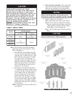
2. Minimum Draft at Breech (Canopy) – The draft
induced by a chimney must create at least a
pressure of 0 (zero) inches water column (“ w.c.)
at the pressure tapping on the canopy mounted
on rear of boiler (see Figure 18). The pressure
at the canopy
cannot
be positive since this could
create a condition that allows fl ue gas by-products
to escape from the draft regulator. A negative
pressure reading up to -.03 inches water column
is acceptable for proper operation. (See Table 6,
Burner Specifi cations at the rear of this manual for
more details)
3. Minimum Overfi re Pressure – The overfi re
pressure is another piece of information that is
often measured, however this should be done for
observation purposes only! The breech pressure
must be used to qualify the draft condition. See
Table 6 for more details as a guide. Actual draft and
temperature measurements may be different then
those values in the table.
D. STACK TEMPERATURE
1. The temperature of the fl ue gases has a signifi cant
effect on the amount of draft created in a vertical
chimney as well as the propensity to create
condensate. The higher the stack temperature, the
greater the amount of draft that can be generated. A
lower stack temperature not only reduces the amount
of draft that can be created but it also increases the
possibility that the fl ue gases could condense in the
chimney connector or stack.
2. NFPA 31 and CSA B139-04 have information to
help the installer make an appropriate choice of
venting materials. In some cases a chimney may
have to be lined to create suffi cient draft. In other
cases, the chimney may have to be lined to prevent
the corrosion of a masonry chimney. Consult
with a chimney specialist knowledgeable on the
requirements for chimney requirements in your area.
N
O
I
T
U
A
C
r
o
y
e
n
m
i
h
c
a
f
o
n
o
i
t
i
d
n
o
c
e
h
t
n
o
t
b
u
o
d
y
n
A
d
n
a
n
o
i
t
a
r
e
n
e
g
e
h
t
t
n
e
v
e
r
p
o
t
y
t
i
l
i
b
a
s
’
t
i
t
s
u
m
,
e
t
a
s
n
e
d
n
o
c
s
a
g
e
u
l
f
f
o
n
o
i
t
a
l
u
m
u
c
c
a
d
e
t
i
n
U
(
1
3
A
P
F
N
o
t
g
n
i
d
r
o
c
c
a
d
e
n
i
l
e
r
e
b
.
)
a
d
a
n
a
C
(
9
3
1
B
A
S
C
r
o
)
s
e
t
a
t
S
N
O
I
T
U
A
C
.
e
d
i
u
g
a
s
a
s
e
l
b
a
t
g
n
i
t
n
e
v
y
e
n
m
i
h
c
e
h
t
e
s
U
-
r
e
d
r
o
b
y
n
a
t
a
h
t
d
e
d
n
e
m
m
o
c
e
r
y
l
h
g
i
h
s
i
t
I
g
n
i
n
i
l
e
r
e
h
t
n
i
t
l
u
s
e
r
d
l
u
o
h
s
n
o
i
t
a
c
i
l
p
p
a
e
n
i
l
t
a
h
t
r
e
n
i
l
e
l
b
a
t
i
u
s
a
h
t
i
w
y
e
n
m
i
h
c
e
h
t
f
o
t
s
n
i
a
g
a
t
c
e
t
o
r
p
o
t
d
n
a
t
f
a
r
d
t
n
e
i
c
i
f
f
u
s
s
e
t
a
e
r
c
.
e
t
a
s
n
e
d
n
o
c
s
a
g
e
u
l
f
y
b
d
e
s
u
a
c
n
o
i
s
o
r
r
o
c
3. Baffl es – The effi ciency of the boiler is based on the
insertion of fl ue baffl es supplied with your product.
Under no circumstances are other baffl es to be
used on this product. The baffl es are installed in
the 2
nd
pass (two inner fl ueways) on the MPO147,
MPO189 and MPO231. The baffl es on the MPO84
are installed in the 3
rd
pass only. Refer to Section
II, Item F, Paragraph 7 for baffl e installation. If
there is any doubt on the application of this boiler
on the intended chimney, consult with your local
code offi cials. At a minimum, remove the baffl es
to increase the stack temperature. See Table 6 for
temperature differential (
∆
T) with baffl es IN and
OUT. In addition, the lower the CO
2
level the
higher the stack temperature.
Figure 18: Smokebox Pressure Tapping for
Checking Draft at Breech
Summary of Contents for MPO Series
Page 6: ...6 Figure 1 MPO 84 Thru MPO 231 Water Boiler ...
Page 22: ...22 Figure 13A Water Boiler Piping for Circulator Zoned Heating System Supply Side Circulator ...
Page 38: ...38 Figure 27 L1 L2 and V1 Head Electrode Positioning and Gun Setting Beckett AFG ...
Page 49: ...49 SERVICE RECORD DATE SERVICE PERFORMED ...
Page 50: ...50 Bare Boiler Assembly ...
Page 52: ...52 Bare Boiler Assembly ...
Page 54: ...54 Jacket Assembly ...
Page 56: ...56 MPO84 Thru MPO231 Water Boilers Trim and Controls ...
Page 58: ...58 Beckett AFG Burner ...
Page 61: ...61 Figure A2 LWCO Location ...


