


37
E.
ADJUST OIL BURNER BEFORE
STARTING.
1. CHECK BURNER AIR BAND, AIR SHUTTER
AND HEAD SETTING (if applicable), readjust if
necessary, see Table 8 at rear of manual.
2. OPEN ALL OIL LINE VALVES.
3. Attach a plastic hose to fuel pump vent fi tting and
provide a pan to catch the oil.
4. OPEN FLAME OBSERVATION PORT COVER
on burner swing door.
F.
START OIL BURNER.
1. Open vent fi tting on fuel pump.
2. PRESS RED RESET BUTTON on front of burner
cover, hold for one (1) second and release to reset
primary control.
high limit automatically resets after the water
temperature drops past the setpoint and through
the differential.
n
o
i
t
c
A
e
s
n
o
p
s
e
R
m
e
t
s
y
S
t
a
t
s
o
m
r
e
h
T
r
o
f
s
ll
a
c
t
a
e
h
.
s
t
r
a
t
s
r
o
t
a
l
u
c
r
i
C
r
e
n
r
u
B
.
d
e
k
c
e
h
c
s
i
e
r
u
t
a
r
e
p
m
e
t
r
e
l
i
o
B
s
i
e
r
u
t
a
r
e
p
m
e
t
r
e
t
a
w
e
h
t
n
e
h
w
s
t
r
a
t
s
e
r
.
g
n
i
t
t
e
s
t
i
m
il
h
g
i
h
w
o
l
e
b
r
e
l
i
o
B
e
h
t
s
d
e
e
c
x
e
t
i
m
il
h
g
i
h
n
e
h
w
s
t
r
a
t
s
e
r
r
e
n
r
u
B
.
f
f
o
d
e
n
r
u
t
s
i
r
e
n
r
u
B
e
h
t
w
o
l
e
b
s
p
o
r
d
e
r
u
t
a
r
e
p
m
e
t
r
e
t
a
w
e
h
t
.
l
a
i
t
n
e
r
e
f
f
i
d
e
h
t
s
u
n
i
m
g
n
i
t
t
e
s
t
i
m
il
h
g
i
h
t
a
t
s
o
m
r
e
h
T
d
e
i
f
s
i
t
a
s
s
i
.
f
f
o
n
r
u
t
r
e
n
r
u
b
d
n
a
r
o
t
a
l
u
c
r
i
C
r
o
r
r
E
n
o
i
t
i
d
n
o
c
s
t
u
p
t
u
o
ll
a
,
d
e
t
c
e
t
e
d
s
i
n
o
i
t
i
d
n
o
c
r
o
r
r
e
n
a
f
I
l
o
r
t
n
o
C
.
f
f
o
s
i
r
e
n
r
u
B
.
n
w
o
d
t
u
h
s
e
r
a
n
e
h
w
s
t
r
a
t
s
e
r
d
n
a
n
o
i
t
c
n
u
f
o
t
s
e
u
n
i
t
n
o
c
.
d
e
t
c
e
r
r
o
c
s
i
r
o
r
r
e
e
h
t
,
e
c
n
e
u
q
e
s
k
c
e
h
c
r
o
r
r
e
e
h
t
g
n
i
r
u
D
d
n
a
r
o
s
n
e
s
e
h
t
n
i
t
f
i
r
d
r
o
f
s
k
c
e
h
c
m
e
t
s
y
s
.
s
n
o
i
t
c
e
n
n
o
c
e
h
t
n
i
n
o
i
s
o
r
r
o
c
Figure 25: L7248C Setpoint and Differential
Switching Action
TABLE 6: L7248C CONTROLLER OPERATING
SEQUENCE
3. TURN ‘ON’ BURNER service switch and
allow burner to run until oil fl ows from vent
fi tting in a SOLID stream without air bubbles for
approximately 10 seconds.
NOTE:
For Primary Control "Pump Priming
Cycle" details, see Paragraph I, No. 2., Step a., Item
ii
.
4. Close vent fi tting and burner fl ame should start
immediately after prepurge is completed. Prepurge
prevents burner fl ame until 15 seconds has elapsed
after initial power is applied to burner. During
prepurge the motor and igniter will operate but the
oil valve will remain closed. Refer to Oil Primary
Control Instructions for more details.
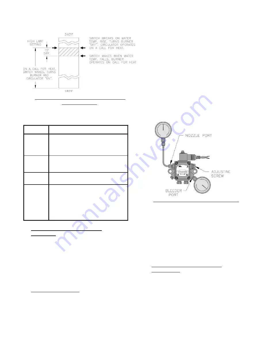
5. Adjust oil pressure.
a. When checking a fuel unit's operating pressure, a
reliable pressure gauge may be installed in either
the bleeder port or the nozzle port. See Figure
26.
Figure 26: Adjusting Fuel Pump Pressure
b. Locate oil pressure adjusting screw and turn
screw to obtain proper pump pressure, refer to
Table 8 at rear of manual.
c. To check the cut-off pressure, deadhead a reliable
pressure gauge onto the copper connector tube
attached to the nozzle port. Run the burner for
a short period of time. Shut the burner off. The
pressure should drop and hold.
d. Remove the gauge and install bleeder port and/or
reconnect the nozzle port line.
G.
ADJUST OIL BURNER WHILE
OPERATING.
(fl ame present)
1. ADJUST DRAFT REGULATOR for a draft of
zero inches (water gauge) in the canopy (see Figure
18) after chimney has reached operating temperature
and while burner is running. (At least fi ve minutes)
See Table 8 at rear of manual for details.
2. READJUST THE AIR BAND on burner for a
light orange colored fl ame while the draft in the
canopy is zero inches water column ("w.c.). Use a
Summary of Contents for MPO Series
Page 6: ...6 Figure 1 MPO 84 Thru MPO 231 Water Boiler ...
Page 22: ...22 Figure 13A Water Boiler Piping for Circulator Zoned Heating System Supply Side Circulator ...
Page 38: ...38 Figure 27 L1 L2 and V1 Head Electrode Positioning and Gun Setting Beckett AFG ...
Page 49: ...49 SERVICE RECORD DATE SERVICE PERFORMED ...
Page 50: ...50 Bare Boiler Assembly ...
Page 52: ...52 Bare Boiler Assembly ...
Page 54: ...54 Jacket Assembly ...
Page 56: ...56 MPO84 Thru MPO231 Water Boilers Trim and Controls ...
Page 58: ...58 Beckett AFG Burner ...
Page 61: ...61 Figure A2 LWCO Location ...