


16
2)
This appliance requires a Special Gas Vent. The product is designed to use Burnham supplied AL 29-4C
®
Stainless
Steel vent system components when utilizing the supplied vent adaptor. The following manufacturers offer similar
AL 29-4C
®
components and are approved for use with this product. The use of these alternate manufacturer’s
venting systems can be utilized by connecting directly to the installed vent pipe (supplied adaptor is not required).
See Table 6.5 for complete list of Burnham Vent System Components.
3)
Install Vent Pipe, Burnham Gasketed Vent System.
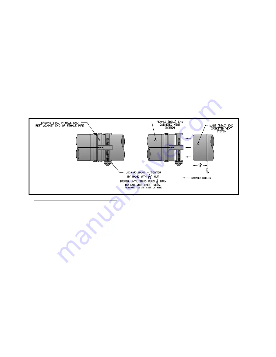
Procedure for Joining Burnham Gasketed Vent Pipe and Fittings. See Fig. 6.7.
a) Wipe the male end of each joint using an alcohol pad to remove any dirt and grease.
b) Align weld seams in pipes and use a slight twisting motion to FULLY insert male end into female end of
joint. Ensure bead in male end of pipe is below locking band and rest against the end of the female pipe. Verify
the factory-installed gasket is not dislodged or cut.
c) Tighten locking band by HAND with a 5/16” nut driver until snug plus ¼ turn. DO NOT SECURE
JOINTS WITH SHEET METAL SCREWS OR POP RIVETS. DO NOT PUNCTURE THE VENT
SYSTEM!
d) Once the installation is complete, operate appliance and inspect all joints to ensure that flue gases and/or
liquid condensate will not escape.
Figure 6.: Burnham Gasketed Vent Joint Detail
4)
Assembly of Flex-L-Intl. Star-34 Vent System:
a) Star-34 General Notes:
• Do not cut Star-34 vent components.
• Support horizontal piping sections at intervals of 48” or less.
• Vertical venting systems must be supported by at least one Star-34 Fire stop. An additional vertical
support is required after any offset.
• Orient Star-34 components so that the arrows on the piping labels are in the direction of flue gas flow.
b) Start assembly of the vent system at the boiler. Remove the hose clamp shipped on the CHG vent collar.
Bend the three hose clamp tabs on this collar outward slightly.
c) Clean the exterior of the male end of the first piece of pipe and the inside of the vent collar on the boiler.
Use a cleaner such as Methyl Ethyl Keytone (MEK) or naptha.
d) On the male end of the pipe, apply a ¼” wide bead of silicone approximately ¼” from the end of the pipe
and another ¼” bead against the joint side of the stop bead (Fig 6.7a).
e) Insert the male end of the pipe into the boiler vent collar until it bottoms out.
f) Apply an additional bead of silicone over the outside of the joint and smooth out.
g) Replace and tighten the clamp on the vent collar.
h) Clean the female end of the first piece of pipe. Also clean the male end of the next piece of pipe.
i) Apply silicone as in step (d) (Fig 6.7b).
j) Align the longitudinal seams of the pipe and insert the male end of the second pipe into the female end of
the first pipe.
k) Insert a Star-34 joiner band into the inlet of the beaded channel. Feed the joiner band in so that it makes its
way around the channel and overlaps by approximately ½” (Fig 6.7b).
Summary of Contents for CHG CHG150
Page 25: ...25 Figure 8 3 Piping Method 1 Heat Indirect Water Heater Figure 8 2 Piping Method 1 Heat Only ...
Page 29: ...29 Figure 8 8 Piping Method 2 Heat Only Figure 8 9 Piping Method 2 Heat Indirect Water Heater ...
Page 36: ...36 Figure 9 1 Wiring Connections Diagram ...
Page 37: ...37 Figure 9 2 Ladder Diagram ...
Page 38: ...38 Figure 9 3 Wiring of Isolation Relay for Control of Two Heating Circulators ...
Page 40: ...40 CHG Series Lighting and Operating Instructions ...
Page 46: ...46 Figure 11 2 Basic Menu Tree ...
Page 54: ...54 SERVICE RECORD DATE SERVICE PERFORMED ...
Page 58: ...58 ...
Page 59: ...59 ...
Page 60: ...60 ...
Page 61: ...61 ...
Page 63: ...63 ...
Page 65: ...65 ...
Page 66: ...66 ...
Page 67: ...67 ...
Page 69: ...69 SERVICE RECORD DATE SERVICE PERFORMED ...
Page 70: ...70 SERVICE RECORD DATE SERVICE PERFORMED ...
Page 71: ...71 SERVICE RECORD DATE SERVICE PERFORMED ...
Page 72: ...9EARS IN 3ERVICE 3ERVICE HARGE AS OF 2ETAIL 0RICE O HARGE ...