B
URK
Technology
RX-4 User’s Manual -- Version 1.01
11
Please note that it is also possible to loop a hot standby connector, or even daisy-chain, from one RX-4
unit to another (any number of them, in fact). The same considerations apply between units as within
units: the Loop OUT of the standby module goes to the Loop IN of the primary module (except for the
AM receiver, where the Loop IN is not functional). In such a case, the units so connected should be
adjacent to one another in the rack, for the shortest possible run of loop cable.
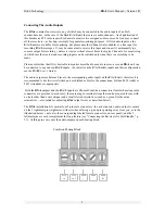
Connecting the Receivers for Hot Standby
Use single-conductor wire to connect the receivers you wish to link in hot standby mode. The wires attach
to the Combicon connectors in the same fashion as the audio output cables, discussed above. On each 5-
pin mating plug, the leftmost pin is Loop IN and the pin immediately to its right is Loop OUT, as
indicated in the figure below. For each individual standby loop, prepare a lead of the proper length and
strip both ends. Attach one end of the wire to the Loop IN pin of the primary receiver’s mating plug;
attach the other end of the wire to the Loop OUT pin on the mating plug of the receiver selected for
standby.
Combicon Mating Block
Repeat the process for as many primary-standby pairs as you require, daisy-chaining the connectors where
you wish a standby unit to be covered by a standby in turn. You may freely connect between separate RX-
4 units, as well as among individual receivers within a single unit, taking care only to avoid connecting to
the Loop IN of the AM receiver’s plug, for the reasons noted above.
When all audio output and loop connections have been fashioned, simply plug the assembled 5-pin
connectors into the appropriate receiver channels; plug the 6-pin Combicons on the other ends of the
cables into the proper channel pairs on the E
ú
A
ú
S back panel. Now you’re ready to power the RX-4 up.
Powering Up
Once all the proper connections are made, you may power the unit up. Note that the RX-4
features no
power switch. As with the E
ú
A
ú
S unit it is designed to work with, the RX-4
is
meant to be powered up at
all times, always supplying audio input to the E
ú
A
ú
S in accordance with the user’s assigned monitoring
Loop
IN
Loop
OUT
Audio
+
Audio
-
Audio
â
Summary of Contents for RX-4
Page 2: ...RX 4 User s Manual Version 1 01 BURK Technology ...
Page 4: ...RX 4 User s Manual Version 1 01 BURK Technology ii ...
Page 17: ...BURK Technology RX 4 User s Manual Version 1 01 13 ...
Page 28: ...RX 4 User s Manual Version 1 01 BURK Technology 24 APPENDIX RX 4 SCHEMATICS ...
Page 29: ...BURK Technology RX 4 User s Manual Version 1 01 25 ...
Page 31: ......
Page 32: ...RX 4 User s Manual Version 1 01 BURK Technology 4 ...
Page 33: ...BURK Technology RX 4 User s Manual Version 1 01 5 ...
Page 34: ...RX 4 User s Manual Version 1 01 BURK Technology 6 ...

