background image

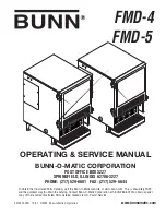
OPERATING & SERVICE MANUAL

BUNN-O-MATIC CORPORATION

POST OFFICE BOX 3227

SPRINGFIELD, ILLINOIS 62708-3227

PHONE: (217) 529-6601   FAX: (217) 529-6644

www.bunnomatic.com

To obtain the Illustrated Parts Catalog, visit the Bunn-O-Matic website, at www.bunn.com. This is absolutely FREE, 

and the quickest way to obtain the catalog. Contact Bunn-O-Matic Corporation at 1-800-286-6070 to obtain a paper 

copy of the required Illustrated Parts Catalog mailed via U.S. Postal Service.


FMD-4

FMD-5

35135.0000D    10/07   ©2003  Bunn-O-Matic Corporation

Summary of Contents for FMD-4

Page 1: ...To obtain the Illustrated Parts Catalog visit the Bunn O Matic website at www bunn com This is absolutely FREE and the quickest way to obtain the catalog Contact Bunn O Matic Corporation at 1 800 286 6070 to obtain a paper copy of the required Illustrated Parts Catalog mailed via U S Postal Service FMD 4 FMD 5 35135 0000D 10 07 2003 Bunn O Matic Corporation ...

Page 2: ... by such individuals whether oral or written do not constitute warranties and should not be relied upon If BUNN determines in its sole discretion that the equipment does not conform to the warranty BUNN at its exclusive option while the equipment is under warranty shall either 1 provide at no charge replacement parts and or labor during the applicable parts and labor warranty periods specified abo...

Page 3: ...ing on thermostat or connecting appliance to power source Use only on a properly protected circuit capable of the rated load Electrically ground the chassis Follow national local electrical codes Do not use near combustibles FAILURE TO COMPLY RISKS EQUIPMENT DAMAGE FIRE OR SHOCK HAZARD READ THE ENTIRE OPERATING MANUAL BEFORE BUYING OR USING THIS PRODUCT THIS APPLIANCE IS HEATED WHENEVER CONNECTED ...

Page 4: ...off valve should be installed in the line before the dispenser Install a regulator in the line when pressure is greater than 100 psi 690 kPa to reduce it to 50 psi 345 kPa The water inlet fitting is 3 8 flare NOTE At least 18 inches of an FDA approved flexible beverage tubing such as reinforced braided polyethylene or silicone before the dispenser will facilitate movement to clean the countertop B...

Page 5: ... the refill error has been investigated see the troubleshooting guide in the Operating and Service Manual and cured the system can be reset by placing the Rinse Run switch in the programming center position momentarily RINSE TIMERS The dispenser is shipped from the factory with the rinse timers disabled To enable the rinse timers remove power from the dispenser remove the lower access panel and re...

Page 6: ...se to decrease or counterclockwise to increase the amount of water 4 Replace appropriate access panels when finished HOPPER MOTOR SPEED PROGRAMING The hopper dispense rate is preset at the factory With 22 tooth gear and auger wire the preset dispense rate is approximately 3 to 5 grams per second With 30 tooth gear and auger wire the preset dispense rate is approxi mately 5 to 7 grams per second Th...

Page 7: ...y into a sink or a container with a minimum of 6 1 2 gallon capacity 6 Make sure drain clamp is closed Then remove drain plug 7 Direct tube into sink or container and open drain clamp Continue draining tank until ALL of the water is out WARNING Be very careful with the draining water because it can be very hot 8 Close drain clamp insert drain plug place drain tube back into machine and replace low...

Page 8: ... to avoid twists and kinks in the tubing Make certain that all plumbing connections are sealed and electrical connections tight and isolated This unit is heated at all times Keep away from combustibles WARNING Exercise extreme caution when servicing electrical equipment Unplug the dispenser when servicing except when electrical tests are specified Follow recommended service procedures Replace all ...

Page 9: ...seonlyBOM replacement part 29329 1000 2 Control Thermostat 3 Tank Heater REMEDY Refer to Service Solenoid Valve Inlet for testing procedures See page 37 Refer to Service Control Board and Probe for testing procedures See page 20 Refer to Service Auger Drive See page 13 15 Remove the strainer and check for obstructions Clear or replace Inspect the tank assembly for ex cessive lime deposits Delime a...

Page 10: ...steel surfaces can initiate corrosive reactions resulting in seri ous leaks 2 Dispense Solenoid Valve 1 Control Board 1 and Probe 2 Solenoid Valve Inlet REMEDY Refer to Service Tank Heater Switch for testing procedures See page 39 Refer to Service Relay for testing procedures See page 40 Refer to Service Control Board 2 for testing procedures See page 22 Inspect the tank assembly for ex cessive li...

Page 11: ...e cycleandcheckthewatertemperature immediately below the dispense tip with a thermometer Reading should be 180 F to 200 F see thermostat temperature settings decal in USER NOTICES on page 3 Refer to Service Whipper Motor for testing procedure See page 27 Refer to Service Frother Compo nents See page 26 Refer to Service Dispense Solenoid Valve for test procedures See page 35 Refer to Service Auger ...

Page 12: ...Water pressure to the dispenser must not exceed 100 psi 690 kPa Install a regulator if necessary to lower the working pressure to ap proximately 50 psi 345 kPa Remove and clean lime off the tank heater See page 38 Refer to Service Fan for testing procedures See page 25 Refer to Service Lamp see page 29 for lamp replacement Refer to Service Lamp Holder for testing procedures See page 29 Refer to Se...

Page 13: ...mostat 31 Rinse Run Switch 32 Hot Cold Switch Optional 33 Solenoid Cold Water Optional 34 Solenoid Dispense 35 Solenoid Inlet 37 Tank Heater 38 Tank Heater Switch 39 Tank Heater Relay 40 Transformer 41 Whipper Motor 27 Wiring Diagram 42 45 FIG 1 AUGER DRIVE COMPONENTS Location Theaugercomponentsarelocatedinsidethebottom part of the hopper except for the auger drive bracket spacer and retaining cli...

Page 14: ... and wiper drive gear 5 from the hopper base 8 7 Remove auger wire 13 by pulling it out the front of the hopper base 8 8 Remove auger drive bracket 6 by unscrewing left hand threads from auger drive shaft 12 9 Slide spacer 7 and auger drive shaft bracket 6 off of the auger drive shaft 12 10 Remove auger drive shaft 12 from hopper base 8 11 Wash components in a mild solution of dish de tergent usin...

Page 15: ...RIVE COMPONENTS FMD 4 FMD 5 P2635 AUGER DRIVE COMPONENTS FMD 4 cont Auger Drive Motor Refer to Fig 2 1 Remove hopper assy 15 and set aside for reas sembly 2 Removethefour 8 32screwssecuringthehopper support plate 11 remove plate and set aside for reassembly 3 Remove the four 8 32 screws located inside the dispenser housing on the lower right front of the auger motor mounting panel 19 securing auge...

Page 16: ...rive shaft 8 Slide washer 8 and auger drive shaft bracket 7 off of the auger drive shaft 5 9 Slide auger drive shaft 5 from auger drive shaft bushing 3 and remove from hopper 10 10 Remove locknut 9 from auger drive shaft bush ing 3 and remove auger drive shaft bushing from hopper 10 11 Wash components in a mild solution of dish detergent using a bristle brush when needed 12 Rinse and dry each item...

Page 17: ...m auger motor 16 7 Remove the four 8 32 screws securing the auger motor to the auger motor mounting bracket 8 Remove auger motor and discard 9 Using four 8 32 screws install new auger motor 16 on mounting bracket 15 10 Install dust seal 17 on auger motor shaft 11 Using four 8 32 locking screws install auger mo tor dust seal and mounting bracket to the rear of the auger motor mounting panel 14 12 R...

Page 18: ...LS SERVICE cont Removal and Replacement 1 Loosen the three 8 32 screws securing the com ponent bracket to the dispenser housing base 2 Pull component bracket out the front of the dis penser far enough so the leads on each ballast can bedisconnectedfromthemainwiringharnessand the door interconnect harness 3 Remove the two 8 32 screws securing each bal last to the rear of the component bracket 4 Rem...

Page 19: ... SERVICE cont Removal and Replacement 1 Remove the thermostat capillary bulb by firmly pulling up on the capillary at the tank lid This will disengage the grommet from the tank lid 2 Loosen the two 6 32 screws securing the ther mostat to the front tank mounting bracket 3 Disconnect the wires from the thermostat 4 Remove thermostat and remove the screws and spacers from the thermostat 5 Discard the...

Page 20: ...fter a delay of approximately 10 seconds 13 Touch the free end of the jumper wire to the dis penser housing The indication must be 0 14 Move the jumper wire away from the housing The indication must again be 120 volts ac for two wire 120 volt models three wire 120 208 volt models three wire 120 240 volt models or 230 volts ac for two wire 230 volt models after a delay of ap proximately 5 seconds 1...

Page 21: ...uitry is operating properly Ifthevoltageisnotpresentasdescribed checkthepink probe wire and green tank wire for continuity CONTROL BOARD CONT Hopper Motor Control Circuitry Stations 1 3 Control Board 1 Stations 4 5 Control Board 2 1 Disconnect the dispenser from the power source 2 Disconnect the six pin connector from J3 of the appropriate control board 3 Check the voltage across pins 5 6 of the s...

Page 22: ...f the wiring harness to J4 of control board 2 10 Check the voltage across the coil terminals of the tank heater relay with a voltmeter Connect the dispenser to the power source The indication must be 0 volts ac If voltage is absent as described proceed to step 11 If voltage is present replace the control circuit board 2 11 Place containers below any three dispenser nozzles 12 Simultaneously initia...

Page 23: ...30 volt models 5 Disconnect the dispenser from the power source If voltage is present as described proceed to 6 If voltage is not present as described refer to the wiring diagram and check the dispenser wiring har ness 6 With a voltmeter check the voltage across the remaining two wires of the dispense switch being tested from the door interconnect wiring harness Connect the dispenser to the power ...

Page 24: ...r door 2 Remove the six 8 32 screws securing the bot tom door cover and remove cover 3 Disconnect the wires on the dispense switch from the door interconnect wiring harness 4 Compress the clips inside the door on the dis pense switch and gently push the switch through the opening 5 Push the new switch into the opening and spread the clips to hold the switch in the door 6 Reconnect the wires to the...

Page 25: ... volts ac for two wire 230 volt models If voltage is present as described replace the fan If voltage is not present as described refer to wiring diagram and check the dispenser wiring harness Removal and Replacement 1 Disconnect the vacuum hose from the fan 2 Remove the two 8 32 locking screws securing the fan to the dispenser housing base plate 3 Disconnect the wires from the fan terminals and di...

Page 26: ...0 240 volt models c 230 volts ac for two wire 230 volt models 4 Disconnect the dispenser from the power source If voltage is present as described replace the motor If voltage is not present as described refer to the wiring diagrams and check the dispenser wiring har ness FIG 18 MIXING WHIPPER CHAMBER COMPONENTS 1 Steam Collector 2 Mixing Chamber 3 Dispense Tip 4 Whipper Chamber 5 O Ring 6 Frother ...

Page 27: ...ining components in a mild solution of dish detergent using a bristle brush 19 Rinse thoroughly and allow to dry before reinstall ing in the dispenser 20 Slide whipper chamber receptacle w seal 7 and O ring 5 on to the motor shaft 21 Rotate the receptacle w seal 7 counterclockwise until it snaps into place on the motor mounting nuts 8 22 Pushfrother 6 ontothemotorshaft makingsure the flat in the f...

Page 28: ...nuity is present as described the switch is operating properly If continuity is not present as described replace the switch RED BLK from Control Board J2 6 GRN from Control Board J2 9 WHI VIO from Control Board J2 1 FIG 21 INCREASE DECREASE SWITCH TERMINALS P1208 Removal and Replacement 1 Open the dispenser door 2 Removethefacenutsecuringtheincrease decrease switch to the whipper motor mounting pa...

Page 29: ...he door wiring harness 7 Rotatelamp 3 90 andremovefromlampholders 2 8 Removethe 6 32screwsecuringthelampholder 2 to be removed remove lamp holder 2 and discard 9 Install new lamp holder 2 and secure with a 6 32 screw 10 Connect the wires on the new lamp holder to the door wiring harness 11 Install lamp 3 into lamp holders 2 and turn 90 until the pins snap in place 12 Install upper door panel 4 lam...

Page 30: ...tarter If continuity is not present as described starter is operating properly Note If continuity tests are both as described and lamp does not light replace the starter SERVICE cont LAMP REPLACEMENT Refer to Fig 22 cont Removal and Replacement Refer to Fig 22 1 Open dispenser door assy 1 2 Remove the four 8 32 screws securing the door lower panel 5 to the door assy 1 3 Disconnect the leads on the...

Page 31: ...yispresentasdescribed thelimitthermostat is operating properly If continuity is not present as described replace the limit thermostat FIG 24 LIMIT THERMOSTAT TERMINALS P1800 BLK to Tank Heater BLK to Control Thermostat 35135 012103 Removal and Replacement 1 Remove all wires from the limit thermostat ter minals 2 Carefully slide the limit thermostat out from under the retaining clip and remove the ...

Page 32: ...he switch is in the center position If continuity is present as described the switch is operating properly If continuity is not present as described replace the switch FIG 26 RINSE RUN SWITCH TERMINALS P1644 GRY to Control Board J2 2 GRN to Control Board J2 9 WHI GRY to Control Board J2 3 BRN BLK to Main Harness BLK from Main Harness BRN BLK to Main Harness Removal and Replacement 1 Open the dispe...

Page 33: ...5 Ifvoltageisnotpresentasdescribed refertotheWiring Diagrams and check the main wiring harness 5 Disconnect the wires from the switch terminals 6 With the switch in the Cold upper position check for continuity between the center termi nal and the bottom terminal With the switch in the Hot lower position check for continuity between the center terminal and the upper termi nal If continuity is prese...

Page 34: ...press the left dispense switch and listen carefully in the vicinity of the solenoid valve for a clicking sound as the coil magnet attracts 7 Disconnect the dispenser from the power source If the sound is heard as described and water will not pass through the solenoid valve there may be a blockage in the water line before the solenoid valve or the solenoid valve may require inspection for wear and ...

Page 35: ...o 5 If voltage is not present as described refer to wiring diagram and check dispenser wiring harness 5 Check for continuity across the solenoid valve coil terminals If continuity is present as described reconnect the wires to the solenoid see Fig 32 proceed to 6 If continuity is not present as described replace the solenoid valve 6 Checkthesolenoidvalveforcoilaction Connectthe dispensertothepower...

Page 36: ...ine from the solenoid valve 6 Remove the 8 32 keps nut securing the solenoid valve bracket to side of the tank Remove solenoid valve 7 Install new solenoid valve and o ring on side of the tank and secure in place with valve mounting bracket and 8 32 keps nut 8 Push the water line onto the tube on bottom of solenoid valve 9 Refer to Fig 32 and reconnect the wires 10 Reinstall side access panels SOL...

Page 37: ...d reconnect the wires VIO from Main Harness SOLENOID VALVE INLET FIG 33 INLET SOLENOID VALVE Location The inlet solenoid is located on the lower left side near the rear panel Test Procedures 1 Disconnect the dispenser from the power source 2 Disconnect the white and violet wires from the solenoid valve 3 Check the voltage across the white and violet wires with a voltmeter Connect the dispenser to ...

Page 38: ...tions in this manual when reconnecting wires 14 Refer to Fig 36 when reconnecting the wires to the tank heater SERVICE cont FIG 36 TANK HEATER TERMINALS P1218 WHI or RED to Main Harness BLK to Limit Thermostat TANK HEATER FIG 35 TANK HEATER Location The tank heater is located inside the tank and secured to the tank lid Test Procedure 1 Disconnect the dispenser from the power source 2 Check the vol...

Page 39: ...enter and the upper terminal With the switch in the OFF upper po sition no continuity should be present between center and upper terminals If continuity is present as described the tank heater ON OFF switch is operating properly If continuity is not present as described replace the switch Removal and Replacement 1 Remove the switch mounting nut on the front of the front panel 2 Remove switch with ...

Page 40: ...et to the dispenser housing base 2 Pull component bracket out the front of the dis penser far enough so the tank heater relay can be disconnected from the main wiring harness 3 Disconnect the tank heater relay from the main wiring harness 4 Remove the two 8 32 screws securing the tank heater relay to the rear of the component bracket 5 Remove and discard the tank heater relay 6 Install new tank he...

Page 41: ...ector at either control board Connect the dispenser to the power source The indication must be 24 volts ac If voltage is present as described the transformer is operating properly If voltage is not present as described replace the transformer Removal and Replacement 1 Loosen the three 8 32 screws securing the com ponent bracket to the dispenser housing base 2 Pull component bracket out the front o...

Page 42: ...42 35135 111103 ...

Page 43: ...43 35135 111103 ...

Page 44: ...44 35135 012103 ...

Page 45: ...45 35135 012103 ...

Page 46: ...I RED WHI ORN WHI YEL WHI BLU GRN WHI BLK WHI WHI BLU WHI BLK BLK BLK BLK RED WHI BLU RED BLK RED RED BLU BLU RED RED RED RED RED RED RED BLU WHI WHI GRN BLU RED BLK BLK BLK WHI BLK STARTER STARTER LAMP 1 BALLAST LAMP 2 BALLAST BLK BLK BLK BLK BLK BLK BLK BLK BRN BLK HOPPER 4 HOPPER 5 M M M SOL M SOL M SOL M SOL M SOL STATION 1 WHIPPER STATION 2 WHIPPER STATION 3 WHIPPER STATION 4 WHIPPER STATION ...

Reviews: