background image

Chapter 5: Advanced Serverboard Setup

5-7

5-5  Installing the Processors and Heat Sinks

!

When handling the processor package, avoid placing direct pressure on 

the label area of the fan.

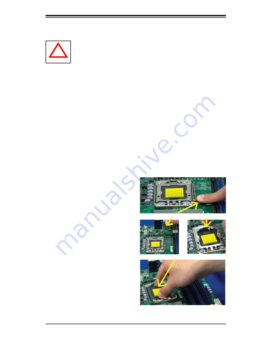
Installing an LGA 1366 Processor 

1.  Press  the  socket  clip  to  release 
the  load  plate,  which  covers  the  CPU 

socket, from its locking position..

2. Gently lift the socket clip to open the 
load plate.

Notes

:

Always connect the power cord last and always remove it before adding, re

-

1. 

moving or changing any hardware components. Make sure that you install the 

processor into the CPU socket before you install the CPU heatsink.

Make sure to install the motherboard into the chassis before you install the 

2. 

CPU heatsink and heatsink fans.

When purchasing a 5500 Series processor or when receiving a motherboard 

3. 

with a 5500 Series processor pre-installed, make sure that the CPU plastic 
cap is in place, and none of the CPU pins are bent; otherwise, contact the 

retailer immediately.

Refer to the 

4. 

Serverboard Features

 Section on page 1-2 for more details on 

CPU support.

3. Hold the plastic cap at its north and 

south  center  edges  to  remove  it  from 

the CPU socket.

Socket clip

Plastic cap

Hold the north and south edges of 

the plastic cap to remove it

Load plate

Summary of Contents for R425-E2

Page 1: ...NOVASCALE R425 E2 Installation and User s Guide REFERENCE 86 A1 53FA 00...

Page 2: ......

Page 3: ...NOVASCALE R425 E2 Installation and User s Guide Hardware August 2009 BULL CEDOC 357 AVENUE PATTON B P 20845 49008 ANGERS CEDEX 01 FRANCE REFERENCE 86 A1 53FA 00...

Page 4: ...s and Acknowledgements We acknowledge the rights of the proprietors of the trademarks mentioned in this manual All brand names and software and hardware product names are subject to trademark and or p...

Page 5: ...ry modules Manual Organization Chapter 1 Introduction The first chapter provides a checklist of the main components included with the ser ver system and describes the main features of the NovaScale R4...

Page 6: ...o this chapter when adding or removing processors or main memory and when reconfiguring the serverboard Chapter 6 Advanced Chassis Setup Refer to Chapter 6 for detailed information on the NovaScale R4...

Page 7: ...1 5 Fans 1 5 Mounting Rails optional 1 5 Power Supply 1 5 Air Shroud 1 6 Other Features 1 6 Chapter 2 Server Installation 2 1 Overview 2 1 2 2 Unpacking the System 2 1 2 3 Preparing for Setup 2 1 Cho...

Page 8: ...Connecting Data Cables 5 4 Connecting Power Cables 5 4 Connecting the Control Panel 5 4 5 4 Back Panel Connectors IO Ports 5 5 5 5 Installing the Processors and Heat Sinks 5 7 Installing an LGA 1366 P...

Page 9: ...herboard 6 15 6 7 Installation Step 5 Install the Air Shroud 6 21 6 8 System Fans 6 23 6 9 Power Supply 6 25 Chapter 7 BIOS 7 1 Introduction 7 1 7 2 Main Setup 7 2 7 3 Advanced Setup Configurations 7...

Page 10: ...Notes viii NovaScale R425 E2 Installation and User s Guide...

Page 11: ...NovaScale R425 E2 www bull com In addition to the serverboard and chassis various hardware components have been included with the NovaScale R425 E2 as listed below One 1 SATA backplane CSE SAS 743TQ...

Page 12: ...ickPath Interconnect QPI 6 4 GT s with a total of up to 51 2 GB s Data Transfer Rate 6 4 GB s per direction Memory 18 240 pin DIMM sockets support up to 144 GB of DDR3 Reg ECC 1333 1066 800 MHz Memory...

Page 13: ...in sleep mode CPU slow down on temperature overheat Pulse Width Modulation PWM Fan Control CPU thermal trip support for processor protection power LED Power up mode control for recovery from AC power...

Page 14: ...PCM 450R BMC Controller PS 2 mouse keyboard ports one COM port and one Serial header Up to ten USB 2 0 Universal Serial Bus six Backpanel USB Ports and four Front Panel Front Accessible USB connection...

Page 15: ...ch NovaScale R4525 E2 chassis comes with a 4U backplane Depending on your order your backplane will accept SAS SATA or SCSI Fans The NovaScale R4525 E2 chassis accepts three system fans and two rear e...

Page 16: ...Chapter 5 for details Air Shroud Air shrouds are shields usually plastic that funnel air directly to where it is needed Always use the air shroud included with your chassis Other Features Other onboa...

Page 17: ...ad to Section 2 5 2 2 Unpacking the System You should inspect the box the system was shipped in and note if it was damaged in any way If the server itself shows damage you should file a damage claim w...

Page 18: ...single rack installation stabilizers should be attached to the rack In multiple rack installations the racks should be coupled together Always make sure the rack is stable before extending a componen...

Page 19: ...s not compromised Mechanical Loading Equipment should be mounted into a rack so that a hazardous condition does not arise due to uneven mechanical loading Circuit Overloading Consideration should be g...

Page 20: ...nstallation instructions that came with the rack unit you are using Identifying the Sections of the Rack Rails The optional rackmount kit includes two rack rail assemblies Each of these as semblies co...

Page 21: ...hassis rail sections you just removed along the side of the chassis making sure the screw holes line up Note that these two rails are left right specific Screw the rail securely to the side of the cha...

Page 22: ...and with the rail guides facing inward Installing the Server into the Rack You should now have rails attached to both the chassis and the rack unit The next step is to install the server into the rack...

Page 23: ...Chapter 2 Server Installation 2 7 Figure 2 4 Installing the Server into a Rack...

Page 24: ...re it says push then lift the latch to release the cover You can then lift the cover from the chassis to gain full access to the inside of the server See Figure 2 5 Checking the Components and Setup Y...

Page 25: ...Chapter 2 Server Installation 2 9 Figure 2 5 Accessing the Inside of the System...

Page 26: ...page 3 6 6 and on if you need to reinstall a CD ROM and or floppy disk drive to the system Depending upon your system s configuration your system may have one or more drives already installed If you...

Page 27: ...to keep you constantly informed of the overall status of the system as well as the activity and health of specific components NovaScale R425 E2 has two buttons on the chassis control panel a reset bu...

Page 28: ...e LEDs These LEDs provide you with critical information related to different parts of the system This section explains what each LED in dicates when illuminated and any corrective action you may need...

Page 29: ...of the SATA drive carrier indicates drive activity A connection to the SATA backplane enables this LED to blink on and off when that particular drive is being accessed Red The red LED to indicate an...

Page 30: ...NovaScale R425 E2 Installation and User s Guide 3 4...

Page 31: ...r you should first power down the system with the operating system first and then unplug the power cords of all the power supply units in the system When working around exposed electrical circuits ano...

Page 32: ...jects from your body which are excellent metal conductors that can create short circuits and harm you if they come into contact with printed circuit boards or areas where power is present Serverboard...

Page 33: ...use Touch a grounded metal object before removing the board from the antistatic bag Do not let components or PCBs come into contact with your clothing which may retain a charge even if you are wearing...

Page 34: ...en the NovaS cale R425 E2 is operating to assure proper cooling Out of warranty damage to the system can occur if this practice is not strictly followed Figure 4 1 Installing the Onboard Battery LITHI...

Page 35: ...ct the data and power cables and install add on cards All motherboard jumpers and connections are also described A layout and quick reference chart are included in this chapter for your reference Re m...

Page 36: ...awings and pictures shown in this manual were based on the latest PCB Revision available at the time of publishing of the manual The motherboard you ve received may or may not look exactly the same as...

Page 37: ...ipment from electric static discharge Precautions Use a grounded wrist strap designed to prevent Electrostatic Discharge ESD Touch a grounded metal object before removing any board from its antistatic...

Page 38: ...I SATA5 Control Panel cable JF1 DVD ROM drive cable IDE 1 USB cable USB2 3 COM Port cable COM2 Important Make sure the cables do not come into contact with the fans Connecting Power Cables The NovaSc...

Page 39: ...specification See Figure 5 4 below for the colors and locations of the various I O ports Figure 5 3 Control Panel Header Pins Figure 5 4 Back Panel Connectors IO Ports NMI x Key Vcc Vcc Vcc Vcc Vcc V...

Page 40: ...anel Connectors 1 Keyboard Purple 2 PS 2 Mouse Green 3 COM Port 1 Turquoise 4 VGA Blue 5 USB 0 6 USB 1 7 IPMI_Dedicated LAN 8 USB 2 9 USB 3 10 USB 4 11 USB 5 12 LAN 1 13 LAN 2 14 Side_surround 15 Blac...

Page 41: ...you install the processor into the CPU socket before you install the CPU heatsink Make sure to install the motherboard into the chassis before you install the 2 CPU heatsink and heatsink fans When pur...

Page 42: ...inst the surface of the socket or its pins to avoid damaging the CPU or the socket 7 With the CPU inside the socket inspect the four corners of the CPU to make sure that the CPU is properly installed...

Page 43: ...lready been applied 2 Place the heatsink on top of the CPU so that the four mounting holes are aligned with those on the retention mechanism 3 Install two diagonal screws ie the 1 and the 2 screws and...

Page 44: ...fan wires from the CPU fan header 3 Using a screwdriver loosen and remove the heatsink screws from the motherboard in the sequence as show in the picture on the right 4 Hold the heatsink as shown in...

Page 45: ...slots Branch 0 Branch 1 Branch 2 3 DIMMs P1 1A P1 2A P1 3A 6 DIMMs P1 1A P1 1B P1 2A P1 2B P1 3A P1 3B 9 DIMMs P1 1A P1 1B P1 1C P1 2A P1 2B P1 2C P1 3A P1 3B P1 3C Memory Population for Optimal Perf...

Page 46: ...k QR Quad Rank 3 1 Reg DDR3 ECC 800 1066 1333 SR DR 3 1 Reg DDR3 ECC 800 1066 QR 3 2 Reg DDR3 ECC 800 1066 SR DR 3 2 Reg DDR3 ECC 800 SR DR QR 3 3 Reg DDR3 ECC 800 SR DR Figure 5 5 DIMM Installation 3...

Page 47: ...stalling an Add on Card Begin by removing the shield for the PCI slot you wish to populate 1 Fully seat the card into the slot pushing down with your thumbs evenly on 2 both sides of the card Finish b...

Page 48: ...he onboard power connection is on Make sure to unplug the power cables before removing or installing components WARNING 1 To prevent damage to the power supply or motherboard please use a power supply...

Page 49: ...rt FP Serial Header FAN 1 8 System CPU Fan Headers Fans 7 8 CPU Fans 1 2 Floppy Floppy Drive IDE IDE Drive JD1 PWR LED Speaker Header Pins 1 3 Power LED Pins 6 7 Onboard Buzzer Pins 4 7 External Speak...

Page 50: ...a 2 No Connection 2 No Connection 3 Ground 3 Ground 4 Mouse KB VCC 5V 4 Mouse KB VCC 5V 5 KB Clocl 5 Mouse Clock 6 No Connection 6 No Connection VCC with 1 5A PTC current limit ATX PS 2 Keyboard and P...

Page 51: ...nal serial connection support See the table on the right for pin definitions Video Connector A Video VGA connector is located above COM Port1 on the IO back plane This connector is used to pro vide vi...

Page 52: ...7 8 9 are on the motherboard to provide front chassis access Cables are not included See the tables on the right for pin defini tions Front Panel USB Pin Definitions USB6 7 8 9 USB 6 8 USB 7 9 Pin De...

Page 53: ...t for IPMI 2 0 All these ports accept RJ45 type cables Note Please refer to the LED Indi cator Section for LAN LED informa tion LAN Ports Pin Definitions Pin Definition Pin Definition 1 P2V5SB 10 SGND...

Page 54: ...Audio Conn Signal 1 Side_Surround 2 Back_Surround 3 CEN LFE 4 Microphone_In 5 Front 6 Line_In CD 10 pin Audio Headers A 4 pin CD header CD1 and a 10 pin Audio header are also located on the motherboar...

Page 55: ...s that are normally lo cated on a control panel at the front of the chassis These connectors are designed specifically for use with the R425 E2 server chassis See the figure below for the descriptions...

Page 56: ...20 of JF1 Refer to the table on the right for pin definitions NMI Button Pin Definitions JF1 Pin Definition 19 Control 20 Ground Power LED The Power LED connection is located on pins 15 and 16 of JF1...

Page 57: ...Pin Definition 13 5V 14 HD Active NIC1 NIC2 LED Indicators The NIC Network Interface Controller LED connec tion for GLAN port 1 is located on pins 11 and 12 of JF1 and the LED connection for GLAN Por...

Page 58: ...o the table on the right for pin definitions Power Fail LED The Power Fail LED connection is located on pins 5 and 6 of JF1 Refer to the table on the right for pin definitions OH Fan Fail LED Pin Defi...

Page 59: ...n pins 1 and 2 of JF1 Momentarily contacting both pins will power on off the system This button can also be configured to function as a suspend button with a setting in the BIOS To turn off the power...

Page 60: ...PU PWR connectors JPW2 JPW3 on the motherboard These power connectors meet the SSI EPS 12V specifica tion In addition to the 24 pin ATX power con nector the 12V 8 pin CPU PWR connectors at JPW2 JPW3 m...

Page 61: ...eter 4 PWR Modulation Fan Headers This motherboard has six chassis system fan headers Fan 1 to Fan6 and two CPU fans CPU1 Fan CPU2 Fan on the motherboard All these 4 pin fans headers are backward comp...

Page 62: ...umper PWR LED Connector Pin Definitions JF1 Pin Setting Definition Pin 1 Anode Pin 2 Cathode Pin 3 NA Internal Speaker The Internal Speaker located at SP1 can be used to provide audible alarms for var...

Page 63: ...te Definition Solid Overheat Blinking Fan fail A CNF1 1394a 1 B CNF2 1394a 2 C Overheat LED JOH1 IEEE 1394a Connection CNF1 and CNF2 provide the IEEE 1394a connections on the motherboard See the table...

Page 64: ...use the SMB connection on your system Power SMB I C Connector Power System Management Bus I C Connector JPI C monitors power supply fan and system temperatures See the table on the right for pin defin...

Page 65: ...quare solder pad on the printed circuit board See the motherboard layout pages for jumper locations Note On two pin jumpers Closed means the jumper is on and Open means the jumper is off the pins GLAN...

Page 66: ...er supply you must completely shut down the system remove the AC power cord and then short JBT1 to clear CMOS Watch Dog Enable Disable Watch Dog JWD is a system monitor that can reboot the system when...

Page 67: ...g is Open to disable the connections See the table on the right for jumper settings Compact Flash Enable A Compact Flash Jumper is located at JIDE1 To use a Compact Flash Card on this motherboard you...

Page 68: ...gs VGA Enable Jumper Settings Jumper Setting Definition 1 2 Enabled default 2 3 Disabled 1394a 1 1394a 2 Enable Use Jumper JPI1 to enable the 1394a connec tions at CNF1 1394a 1 CNF2 1394a 2 on the mot...

Page 69: ...100 Mbps Amber 1 Gbps IPMI Dedicated LAN LEDs In addition to LAN 1 LAN 2 an IPMI Dedicated LAN is also located on the IO Backplane The amber LED on the right indicates activity while the green LED on...

Page 70: ...ing components See the table at right for more information A Onboard PWR LED B BMC Heartbeat LED Onboard PWR LED DP4 Settings LED Color Definition Off System Off PWR cable not connected On System Powe...

Page 71: ...that does not have twisted wires always connects to drive B Floppy Connector The floppy connector is located next to the Super I O chip on the motherboard See the table on the right for pin defini tio...

Page 72: ...st Data 14 17 Host Data 0 18 Host Data 15 19 Ground 20 Key 21 DRQ3 22 Ground 23 I O Write 24 Ground 25 I O Read 26 Ground 27 IOCHRDY 28 BALE 29 DACK3 30 Ground 31 IRQ14 32 IOCS16 33 Addr1 34 Ground 35...

Page 73: ...SATA 5 located on the motherboard These ports provide serial link signal connections which are faster than the connections of Parallel ATA See the table on the right for pin definitions Serial ATA Por...

Page 74: ...5 40 NovaScale R425 E2 Installation and User s Guide...

Page 75: ...r and Front Cover Step 2 Configure the Storage Module Step 3 Install Hard Drives Step 4 Install Motherboard Step 5 Install Air Shroud and Check Airflow General Maintenance General Maintenance Systems...

Page 76: ...ver To remove the chassis cover 1 Push the cover latch button to release the latch handle 2 Pull the cover off the chassis using the latch handle Figure 6 1 Removing the Chassis Cover To replace the c...

Page 77: ...es The cover can be locked to prevent unauthorized access The key to this lock is shipped with the system To remove the front cover 1 Unlock the front cover using the key shipped with the system 2 Pul...

Page 78: ...r Rack Configuration The R425 E2 chassis is shipped in tower mode and can be immediately used as desktop server If the chassis is to be used in a rack you must turn the storage module 90 degrees This...

Page 79: ...the storage module to any component in the chassis 3 Push the storage module release lever This lever unlocks the storage mod ule 4 Grasp the external edges of the storage module and pull the unit fr...

Page 80: ...n be set up one of three ways A Add up to three extra hard drives to the drive trays B Add up to three peripheral drives CD ROM DVD ROM etc drive trays C Add five hot swappable hard drives to the stor...

Page 81: ...dd up to three hard drives to the drive trays 1 Open the chassis cover 2 Locate the drive tray release tab for the slot you want to place the peripheral drive 3 Push the drive tray toward the front of...

Page 82: ...I depending on your motherboard The hard drive may not completely fill the tray 5 Secure the hard drive to the tray with four screws from the bottom 6 Slide the hard drive into the chassis until the t...

Page 83: ...pheral drives DVD ROM CD ROM floppy drive etc to the drive trays 1 Open the chassis cover 2 Locate the drive tray release tab for the slot you want to place the peripheral drive 3 Push the drive tray...

Page 84: ...ws from each side 5 Attach the rails to a DVD ROM CD ROM floppy drive or other peripheral The rails should fit any standard sized peripherals 6 Slide the peripheral into the chassis until the tray cli...

Page 85: ...ard drives The mobile rack goes into the storage module which goes into the chassis For more information on mobile rack installation and use refer to the appendix located at the end of this manual 1 O...

Page 86: ...ach the rails to a DVD ROM CD ROM floppy drive or other peripheral The rails should fit any standard sized peripherals Figure 6 12 Remove the Hard Drive Rails Figure 6 13 Add Hard Drive Rails to Stora...

Page 87: ...e chassis These carriers also help promote proper airflow for the drive bays 1 Unlock and open the chassis cover 2 Press the release button to extend the drive tray handle 3 Using the handle pull the...

Page 88: ...sert the hard drive into the chassis To do this 7a Press the hard drive release button to extend the drive tray handle 7b Insert the hard drive into the chassis and close the handle to lock the hard d...

Page 89: ...sis I O Shield To install the I O shield 1 Review the documentation that came with your motherboard Become familiar with component placement requirements and precautions 2 Open the chassis cover 3 Cho...

Page 90: ...event short circuits by securing space between the motherboard and the chassis surface The R425 E2 chassis packaging includes optional standoffs hexagon shaped posts These standoffs accept the rounded...

Page 91: ...quired by your motherboard install standoffs in any areas that do not have a permanent standoff To do this A Place a hexagonal standoff screw through the bottom the chassis B Secure the screw with the...

Page 92: ...ard Drive power cable 2 backplane Each cable has 3 connectors two Hard Drive HDD and one Floppy Drive FDD Attach the HDD connectors to the backplane If you are using a Super Micro backplane the FDD co...

Page 93: ...tall add on cards to the chassis such as PCI cards To install add on and expansion cards 1 Locate the release tab on the top of the PCI bracket 2 Gently apply pressure in the middle of the release tab...

Page 94: ...racket and moth erboard To do this slide the PCI card with L bracket into the PCI slot and secure the card to the motherboard 6 Push the PCI bracket release tab down until it locks into place with an...

Page 95: ...o set up NOTE The air shroud includes tabs that can be removed if motherboard compo nents prevent the air shroud from fitting securely Remove tabs only if necessary To install the air shroud 1 Remove...

Page 96: ...mended server parts 3 Make sure no wires or foreign objects obstruct air flow through the chassis Pull all excess cabling out of the airflow path or use shorter cables The control panel LEDs inform yo...

Page 97: ...place a system fan 1 Open the chassis cover and determine which fan has failed Because the fans are hot swappable the chassis does not have to be powered down 2 Press the fan release tab and lift the...

Page 98: ...Figure 6 24 Rear Chassis Fans To replace a rear chassis fan 1 Press the rear fan release tab 2 Pull the fan from the chassis top first 3 Place the new fan in the chassis bottom first 4 Push the fan fu...

Page 99: ...en the first fails If your system has only one power supply the system shuts down in the unlikely event of a power failure 6 9 Power Supply To replace the power supply 1 Power down the server and unpl...

Page 100: ...6 26 NovaScale R425 E2 Installation and User s Guide Notes...

Page 101: ...be configured Options in blue can be configured by the user The right frame displays the key legend Above the key legend is an area reserved for a text mes sage When an option is selected in the left...

Page 102: ...Do not upgrade the BIOS unless your system has a BIOS relat ed issue Flashing the wrong BIOS can cause irreparable damage to the system In no event shall Supermicro be liable for direct indirect spec...

Page 103: ...ate when this BIOS was completed AMI BIOS Core Version This item displays the revision number of the AMI BIOS Core upon which your BIOS was built Processor The AMI BIOS will automatically display the...

Page 104: ...eeded for system boot The options are Enabled and Disabled QuietBoot Mode This option allows the bootup screen options to be modified between POST messages or the OEM logo Select Disabled to display t...

Page 105: ...not function as bootable devices The options are Enabled and Disabled Power Configuration Power Button Function If set to Instant_Off the system will power off immediately as soon as the user hits th...

Page 106: ...ptions are Disabled and Enabled Adjacent Cache Line Prefetch Available when supported by the CPU The CPU fetches the cache line for 64 bytes if this option is set to Disabled The CPU fetches both cach...

Page 107: ...urbo Mode to boost system performance The options are Enabled and Disabled Intel C STATE Tech If enabled C State is set by the system automatically to either C2 C3 or C4 state The options are Disabled...

Page 108: ...at the system has detected The available options are Auto Force DDR 800 Force DDR 1066 and Force DDR 1333 Memory Mode The options are Independent Channel Mirror Lockstep and Sparing Independent All DI...

Page 109: ...ep is in 0 5 C increment The default is 006 Press or on your keyboard to change this value Inlet Temperature This is the temperature detected at the chassis inlet Each step is in 0 5 C increment The d...

Page 110: ...l VT d Select Enabled to enable Intel s Virtualization Technology support for Direct I O VT d by reporting the I O device assignments to VMM through the DMAR ACPI Tables This feature offers fully prot...

Page 111: ...cy USB device is installed on the motherboard and vise versa The settings are Disabled Enabled and Auto USB 2 0 Controller Select Enabled to activate the onboard USB 2 0 controller The options are Ena...

Page 112: ...feature is available when the option RAID is selected Select Intel to enable Intel s SATA RAID firmware to configure Intel s SATA RAID settings Select Adaptec to enable Adaptec s SATA RAID firmware t...

Page 113: ...he IDE drive performance by increasing the amount of data transferred Only 512 bytes of data can be transferred per interrupt if Block Mode is not used Block Mode allows transfers of up to 64 KB per i...

Page 114: ...r rate of 16 6 MBs Select UDMA0 to allow the BIOS to use Ultra DMA mode 0 It has a data transfer rate of 16 6 MBs It has the same transfer rate as PIO mode 4 and Multi Word DMA mode 2 Select UDMA1 to...

Page 115: ...IDE BusMaster When enabled the BIOS uses PCI bus mastering for reading writing to IDE drives The options are Disabled and Enabled Load Onboard LAN1 Option ROM Load Onboard LAN2 Option ROM Select Enab...

Page 116: ...1 Flow Control This feature allows the user to set the flow control for Console Redirection The options are None Hardware and Software Redirection After BIOS POST Select Disabled to turn off Console R...

Page 117: ...he Default Alarm Select this setting if you want the CPU overheat alarm including the LED and the buzzer to be triggered when the CPU tempera ture reaches about 5 C above the threshold temperature as...

Page 118: ...may be factors contributing to this condition but the CPU is still within its normal operating state and below the CPU Temperature Tolerance The motherboard fans and CPU will run normally as configur...

Page 119: ...through Fan8 Voltage Readings The following voltage readings will be displayed CPU1 Vcore CPU2 Vcore 5Vin 12Vcc V VP1 DIMM VP2 DIMM 3 3Vcc V and Battery Voltage ACPI Configuration Use this feature to...

Page 120: ...agement software and platform hardware This is an informational feature which returns the status code of the BMC micro controller High Performance Event Timer Select Enabled to activate the High Perfo...

Page 121: ...SEL Entry Number SEL Record ID SEL Record Type Timestamp Generator ID Event Message Format User Event Sensor Type Event Sensor Number Event Dir Type Event Data Clear BMC System Event Log Clear BMC Sys...

Page 122: ...ddress as shown in the following graphics Channel Number Enter the channel number for the SET LAN Config com mand This is initially set to 1 Press or on your keyboard to change the Channel Number Chan...

Page 123: ...rm i e 192 168 10 253 The value of each three digit number sepa rated by dots should not exceed 255 as shown in the screen below Parameter Selector Use this feature to select the parameter of your IP...

Page 124: ...16 0 9 A B C D E F separated by dots i e 00 30 48 D0 D4 60 Current Mac Address in BMC This item displays the current Mac address used for your IPMI connection Subnet Mask Configuration Subnet masks t...

Page 125: ...www intel com The options are No Delay 30 sec 60 sec 1 5 min 2 0 min Startup Delay This feature enables or disables startup delay The options are Enabled and Disabled PEF Startup Delay This sets the...

Page 126: ...I BIOS provides a Supervisor and a User password If you use both pass words the Supervisor password must be set first Supervisor Password This item indicates if a Supervisor password has been entered...

Page 127: ...and press Enter to access the submenu and then type in a new User Password Clear User Password Available only when User Password has been set This item allows you to clear a user password after it has...

Page 128: ...allows the user to specify the boot sequence from all available hard disk drives The settings are Disabled and a list of all hard disk drives that have been detected i e 1st Drive 2nd Drive 3rd Drive...

Page 129: ...and reboot the computer Select Discard Changes and Exit from the Exit menu and press Enter Discard Changes Select this option and press Enter to discard all the changes and return to the AMI BIOS Uti...

Page 130: ...7 30 NovaScale R425 E2 Installation and User s Guide Notes...

Page 131: ...up process The error messages normally appear on the screen BIOS Error Beep Codes Beep Code Error Message Description 1 beep Refresh Circuits have been reset Ready to power up 5 short beeps 1 long bee...

Page 132: ...A 2 NovaScale R425 E2 Installation and User s Guide Notes...

Page 133: ...low and can be installed in smaller chassis In addition the cables used in PATA can only extend to 40cm long while SATA cables can extend up to one meter Overall SATA provides better functionality tha...

Page 134: ...the default settings for the BIOS 3 Use the arrow keys to select the Main section in BIOS 4 Scroll down to SATA Control Mode and press the Enter key to select Enhanced 5 Scroll down to SATA RAID Enab...

Page 135: ...Adaptec RAID Configuration Utility ARC The Adaptec RAID Configuration Utility an embedded BIOS Utility includes the following Array Configuration Utility Use this utility to create configure and mana...

Page 136: ...ation and User s Guide Managing Arrays Select this option to view array properties and configure array settings To select this option using the arrow keys and the enter key select Managing Arrays from...

Page 137: ...may make any data on the disk inaccessible If the drive is used in an array you may not be able to use the array again Do not configure a disk that is part of a boot array To determine which disks are...

Page 138: ...the drives you want to configure and press Insert 3 The drive you ve selected will appear in the Selected Drives Dialog Box on the right as shown below Repeat the same steps until all drives that you...

Page 139: ...Appendix B Adaptec HostRAID B 7 5 Read the warning message as shown in the screen below 6 Make sure that you have selected the correct disk drives to configure If cor rect type Y to continue...

Page 140: ...Note It is recommended that you configure devices before you create arrays To create an array 1 From the main menu shown on page B 4 select Create Array 2 Select the disks for the new array and press...

Page 141: ...ault setting 4 The item Create RAID via allows you to select between the different ways of creating methods for RAID 0 and RAID 1 The following table gives examples of when each is appropriate Note If...

Page 142: ...fferent sizes in a RAID However you can only select a smaller drive as the source or first drive during a build operation 5 When migrating from single volume to RAID 0 migrating from a larger drive to...

Page 143: ...erisk will appear next to the bootable array as shown in the picture below Deleting a Bootable Array To delete a bootable array 1 From the Main menu select Manage Arrays 2 From the List of Arrays sele...

Page 144: ...hotspare and press Insert and then press Enter 3 Press Yes when the following prompt is displayed Do you want to create spare Yes No The spare you have selected will appear in the Selected drives Menu...

Page 145: ...d hit Enter as shown on the previous page 2 From the List of Arrays dialog box shown below select the array you want to view and press Enter The Array Properties dialog box appears as shown below show...

Page 146: ...erform a Rebuild to restore its functionality For a critical array rebuild operation the optimal drive is the source drive Note 2 If no spare array exists and a hard disk drive fails you need to creat...

Page 147: ...and press delete 3 In the Array Properties dialog box select Delete and press Enter The fol lowing prompt is displayed Warning Deleting the array will render array unusable Do you want to delete the...

Page 148: ...ble you to format or verify the media of your Serial ATA hard disks To access the disk utilities 1 From the Adaptec RAID Configuration Utility Menu select Disk Utilities as shown above and press Enter...

Page 149: ...actory and do not need to be low level formatted again 3 When the screen shown below displays select Format Disk and press Enter The following screen appears 4 Read the warning message when it appears...

Page 150: ...edia 3 When the screen shown above displays select Verify Disk Media and press Enter 4 A message will display indicating that the selected drive will be scanned for media defects Select Yes and hit En...

Page 151: ...dix B Adaptec HostRAID B 19 To Exit Adaptec RAID Configuration Utility 1 Once you have completed RAID array configurations press ESC to exit The following screen will appear 2 Press Yes to exit the Ut...

Page 152: ...B 20 NovaScale R425 E2 Installation and User s Guide...

Page 153: ...at PnP DMI 2 3 USB Keyboard support and SMBIOS 2 3 Memory Eighteen 240 pin DIMM sockets support up to 144 GB of DDR3 Registered ECC 1333 1066 800 MHz Memory modules with maximum of 8 GB per DIMM modul...

Page 154: ...C 2 NovaScale R425 E2 Installation and User s Guide Notes...

Page 155: ......

Page 156: ...BULL CEDOC 357 AVENUE PATTON B P 20845 49008 ANGERS CEDEX 01 FRANCE REFERENCE 86 A1 53FA 00...

Reviews: