46
- Fixing the machine to a workbench.
The machine must be screwed to a workbench.
■
Mark the position of the mounting holes (A)
on the workbench.
■
Drill holes at each of the marked positions,
adjusting the diameter and depth of the holes to
the screws used.
■
Place the machine on the workbench and
insert the screws into the mounting holes.
■
Firmly tighten the screws.
- Information to set the minimum size of
the pieces to be cut
Minimal workpiece sizes (= all workpieces that
can be clamped left or right from the saw blade
with the provided quick-action clamp “E”
160 x 30 mm (length x width)
- Information on the maximum cross
section of a workpiece in a cross
Bevel
Miter angle
0°
45°
0°
208 mm
x 60 mm
208 mm
x 35 mm
45°
208 mm
x 35 mm
135 mm
x 35 mm
- The outer diameter ranges, the bore
diameter and the thickness of the
blades can be used
Blade Diameter
210mm
Bore diameter
25.4 mm
Blade thickness
2.8 mm
- The maximum depth of cut
Cutting capacity, max. (0°/0°): 208x60 mm
WARNING: Packaging
materials are not toys!
Children must not play with
plastic bags! Danger of
suffocation!
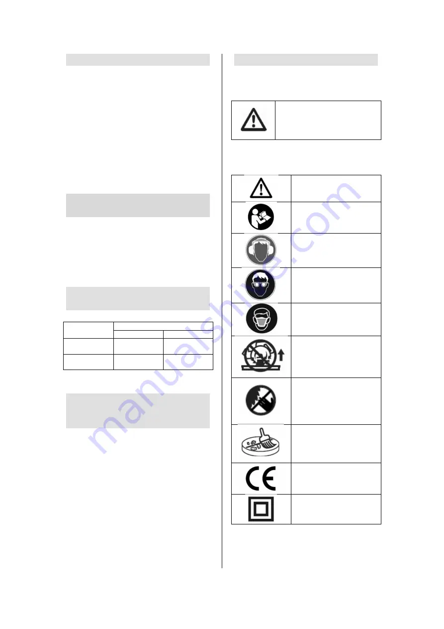
Symbols
Warning / Danger!
Read manual before use.
Wear ear protection.
Wear eye protection.
Always wear a dust
mask.
To avoid injuries caused by
projected keep the
machine head downwards
after cutting until the blade
is completely stopped.
Keep hands away from
the cutting area while the
machine is running.
Danger of injury when
coming in contact with the
saw blade.
For your safety, remove the
chips and other small
pieces on the table before
starting work.
In accordance with
essential applicable
safety standards of
European directives
Double insulated
Summary of Contents for 5411074157999
Page 2: ...2...
Page 3: ...3 Remplacement de la lame de scie Vervangen van de zaag Changing the saw blade...
Page 4: ...4 LASER...
Page 49: ...49...
Page 50: ...50...
Page 51: ...51...
Page 52: ...52...
Page 54: ...54...
Page 58: ...58...


