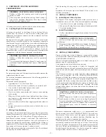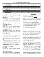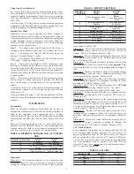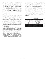
Take a minute to study the LAT Limit table. Note that the limits
are the final shutdown temperatures, but actions begin earlier.
First, at levels 1 and 2, closed dampers begin to open gradually,
followed at level 3 by staging down of multi stage equipment, if it
exists. Under most limit challenges, the system will stabilize
between 1 and 3 due to opening of closed dampers.
CAUTION:
UNIT DAMAGE HAZARD
Failure to follow this caution could result in unit damage.
Setting LAT limit too high can shorten the life of the
HVAC equipment.
Automatic Checkout
An automatic checkout procedure is provided which will exercise
dampers, heating, and cooling in that order. It is described under
the Understanding System Operation section in Installer Test
Mode. This may be used or the system may be checked out
manually by creating thermostat calls. When using thermostats,
remember that only the calling zoning dampers will be open. This
provides the means to select which dampers are open for any
heating or cooling call. It is advisable that the initial checkout be
made with all dampers open before the bypass is set. This can be
done by temporarily setting Switch 5 to ON (disable zoning) and
controlling the equipment from the Zone 1 thermostat. When the
equipment is operating satisfactorily, return Switch 5 to OFF and
proceed to the next section.
Bypass Adjustment
The bypass should be set to the highest possible pressure setting
consistent with an acceptable air noise level. To set, operate the
system with a call from the smallest zone at its highest airflow
(highest may be either heating or cooling). This condition forces
the largest amount of air through the smallest duct, creating the
highest static pressure at the bypass. Adjust the bypass pressure
setting so that the bypass stays closed. Then check to determine if
the level of noise and
″
blow
″
in that zone is acceptable. If it is
unacceptable, reduce the bypass pressure setting (see bypass
instructions for how to adjust) until it just begins to crack open.
Check again, continuing the process until an acceptable noise and
″
blow
″
level is reached.
If, under this condition, the LAT approaches its limit, the system
will open the other closed dampers until the LAT reaches an
acceptable level. This operation is acceptable. The system will
automatically open dampers enough to keep the LAT at a safe
value, and will do it only when the zone demands require it. You
may observe the limit level on the status LED (if it is above zero).
If it stabilizes at a value of higher than 2, an overly small duct
system is indicated and it would be desirable to raise the bypass
pressure setting, if possible.
Error Codes
The status LED indicates normal operation, problems, and
LAT/HPT limit status according to a two digit code. The first digit
flashes its number, followed by a 2 second pause, followed by the
second digit, followed by a 4 second pause. The cycle the repeats.
The codes are:
TABLE 6—ERROR CODES
ON CONTINUOUSLY
NO PROBLEMS
11 - 17
LAT limit level 1 - 7
21 - 27
HPT limit level 1 - 7
31
LAT shorted
32
LAT open
33
HPT open
34
HPT shorted
41
Invalid: Sw 9=ON; Sw 10=OFF
—8—
Summary of Contents for ZONEBB3Z
Page 11: ...11...


