


circuit from R to G. The ICM adjusts airflow down to a lower
CFM for maximum dehumidification for a period of 10 minutes. If
this call continues, outdoor section and ICM shut off for 10
minutes. If super dehumidification call continues, lower CFM and
outdoor section operation will again resume for another 10
minutes.
E.
Electric Heat Heating Mode
Thermostat closes circuit R to W1 & W2.
The terminal block positions W1 and W2 are tied together by
jumper. J2 is provided for field staging of electric heater banks
through use of thermostats. When staging is a requirement, remove
J2 jumper and wire in thermostats as is the common practice with
other fan coils. To ensure motor operation if any 1 of the inputs is
energized, motor will sense input W1 or W2 and run.
F.
Heat Pump Heating Mode—Single Speed or
2-Speed High
Thermostat closes circuit R to Y/Y2 for single speed. A circuit
from R to Y1 is also required for 2-speed high. The Y/Y2 &Y1
signal is sent to ICM2.
G.
Heat Pump Heating Mode—Two-Speed Low
Thermostat closes R to Y1. The Y1 signal is sent to ICM2.
H.
Heat Pump Heating With Auxiliary Electric Heat
Thermostat closes circuits R to Y/Y2 and/or R to Y1 with R to W1
or W2 (and R to O in the case of defrost).
The terminal block positions W1 and W2 are tied together by
jumper. J2 is provided for field staging of electric heater banks
through use of thermostats. When staging is a requirement, remove
J2 jumper and wire in thermostats as is the common practice with
other fan coils. To ensure motor operation if any 1 of the inputs is
energized, motor will sense input W1 or W2 and run.
In the event that electric heating is called for by thermostat while
heat pump is also operating in either heating or defrost mode,
electric heating signal will appear at motor connector pins 6 and 7
(W1) and/or pins 4 and 5 (W2) as described previously. If
necessary, the motor will modify its airflow output to provide an
airflow which is defined as safe for operation of electric heater.
I.
CFM Select Configuration Taps
The CFM Select taps are used by installer to configure system. The
ICM2 is capable of discerning half cycle sine wave on some of its
inputs and uses this capability to modify its operation to a
pre-programmed table of airflows and can be modified in response
to other inputs such as the need for de-humidification.
J.
ICM2 Control Power
The ICM2 control power is supplied from R circuit through
printed-circuit runs to motor control connector pin 8, through
motor control harness to motor. The C side of low-voltage control
power circuit is connected by printed-circuit runs to motor
connector pins 9, 10 and 11 then through motor control harness to
motor.
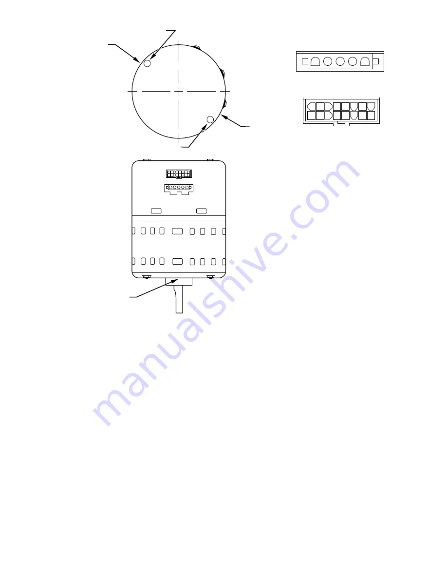
Fig. 23—FK4C and FV4A ICM2.3 Motor
A98201
1
2
3
4
5
9
1 2 3 4 5 6 7 8
10 11 12 13 14 15 16
POWER CONNECTOR
CONTROL CONNECTOR
OPTIONAL SAFETY GROUND
DRAIN HOLE
DRAIN HOLE
OPTIONAL SAFETY GROUND
ENDSHIELD
DRAIN HOLE
CONTROL
POWER
—29—


